 Advanced Manufactured Electronics Projects By Mike, K4ICY Advanced Manufactured Electronics Projects By Mike, K4ICY Weekend Radio Click Here for More Electronics Projects and Tutorials By Mike Maynard, K4ICY Li-Ion / Li-Po Battery Management Board A small BMS capable of providing portable power to your Arduino projects and more. This is an experimental WORK IN PROGRESS project - I can guarantee nothing so build at your own risk!. PCB manufacturing and SMD/SMT component placement is provided below which can be done by a prototyping company such as JLCPCB. Version 2 - Revision 6.i SPECS [Updated 09/23/21] :::: Dimensions: 30mm x 65mm (Version 1 - Revision 4.g had dimensions: 36mm x 65mm) Input: Two Sources - 1) 1S1P/1S2P/... (1 battery, series configuration -by- 1 or more in parallel) Lithium-Ion (18650 type cells) |or| single pouch Lithium Polymer cell rated at (at least) 1,300 mWh each. 2) Bypass for line-power USB charger source which must be rated at greater than 2A of output at 5 volts. Keep using your device even while charging! The switching power supplies used for Raspberry Pi's work great. Output: 2V - 15V adjustable via trimmer. Max output (with load) is dependent on battery configuration/availability at no greater than 2A, current reduced as expected as voltage output increases. (More data to follow.) FEATURES:::: • Single pushbutton toggle on/off (ground-referenced switch line provided by user or host device) as well as a microcontroller shut-off control input (Referenced Low to shut-off.) • Li-Ion/Li-Po operation and 500ma or 1000ma* controlled charging. (*PROG resistor determines rate; 100ma - 1000ma) • Host device continuous operation while charging (battery out of circuit while charging.) • On-board Battery Charge and Ready indicator LEDs, access to external LED indicators. • Battery protection (except thermal), also BMS and device protection measures including over/under current, over/under voltage, reverse polarity and short circuit. • Fine-Pitch Adjustable output voltage between 2v - 15v (2A optimal at 5V - still requires testing) Version 2 - Revision 6.h - Iterative Improvements [Updated 09/07/21] :::: 1) The 555 Timer-based soft latch circuit was replaced by a low-voltage D-type Flip-Flop divider configuration with a Schmitt Inverter input. This should offer more reliable latching over the 555 circuit with more immunity from stray capacitance. 2) A Schottky diode in-line with the +VBatt source was originally used for path steering which imposed a 0.5v voltage drop, but has now been replaced with a bidirectional mosfet switch which should present a drop of only around 0.04v. (the circuit has, as of yet only been tested with non-SMD components.) 3) An option for either of two charging current rates: 500ma or 1000ma, has been added via the [SJ3] jumper. 4) An option for using external LEDs [via 3-pin header] for charge status can now be implemented in your host project by severing [SJ1] and [SJ2] jumpers 5) Resistor values changed on voltage-boost feedback network - because the supplier was out of the 1M trimmers. 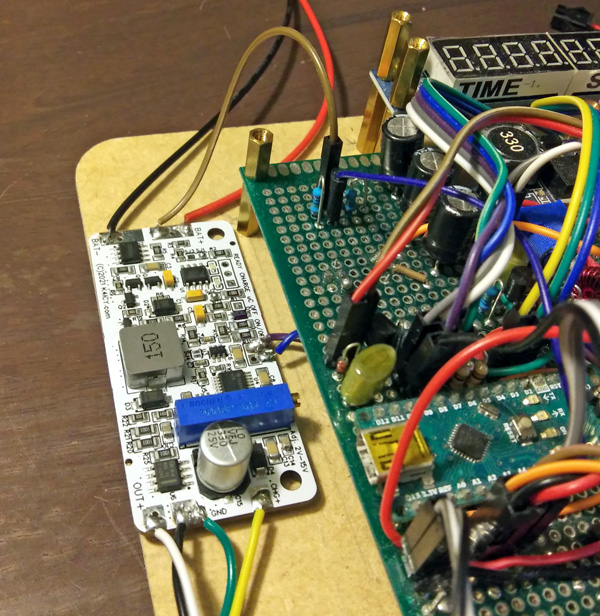 Shown above is my [Version 2 - Revision 6.i] BMS prototype powering my Columns for Arduino game. Dimensions are a little more compact than the one shown in the photo below, but with a few minor improvements. As shown, the hacked former BMS (blue PCB) has been removed. I further implementation, this will be a daughter board of the Columns mother board. 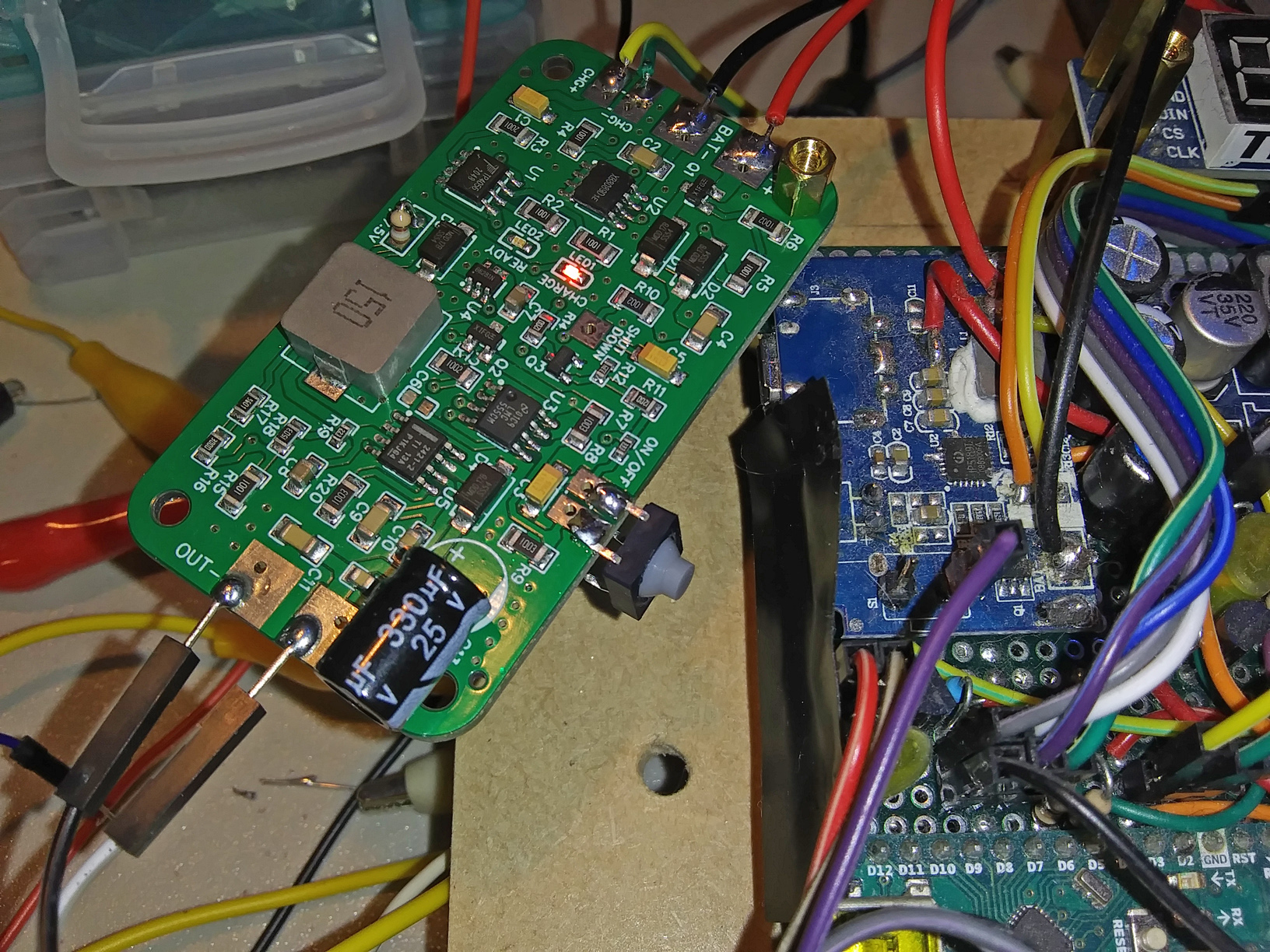 Shown above is my [Version 0 - Revision 2.c] BMS prototype powering my Columns for Arduino game, replacing the hacked power bank board, (blue one to the right.) In case you might be interested, the hacked Jackery BMS (on right) uses an IP5189T, (which has the charge controller and boost converter included,) as well as other 'jellybean' components including a pretty standard battery protection IC and a 3.3v LDO regulator to power the IC; absolutely nothing proprietary, which is the way you'll find it with many generic power bank BMS boards. The only problem was that I found that circuit to be a bit finicky when faced with sudden current rushes from my game. Feel free to hunt down the spec sheets on components making up your banks, you may find that designing your own BMS isn't as hard as you thought once you learn the basics. WARNING!!! Lithium-based batteries must be handled properly to prevent accident, injury and death. Explosions and highly energetic fires are likely with batteries that are overcharged, over-depleted, short circuited, physically damaged and etc. I cannot warranty or guarantee the safety or predictable operation of any devices constructed using my schematics, Gerber files, Bill of Materials or etc. - Builder proceeds at their own assumed risk and liability with appropriate fore-knowledge and training. RESOURCES:::: Adafruit has a comprehensive guide to Lithium-based battery use, particularly for the maker market as well as inexpensive BMS/charging breakout board offerings. Visit: https://learn.adafruit.com/li-ion-and-lipoly-batteries SCHEMATIC & CIRCUIT DESCRIPTION:::: Many of the core component (ICs) are essentially little "black boxes" with specialized functions. However, the component functionality can be found in numerous competing packages from varying manufacturers. You may design your own circuits for academic enjoyment, of course, but the established design of commercially available circuits to safely handle Lithium batteries stem from research and testing. Adhere to any information available from the specification data sheets to most safely and optimally enjoy lithium battery technology.. Version 2 - Revision 6.i Schematic : 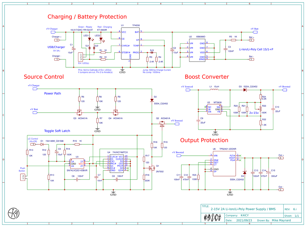 Version 1 - Revision 4.g Schematic : 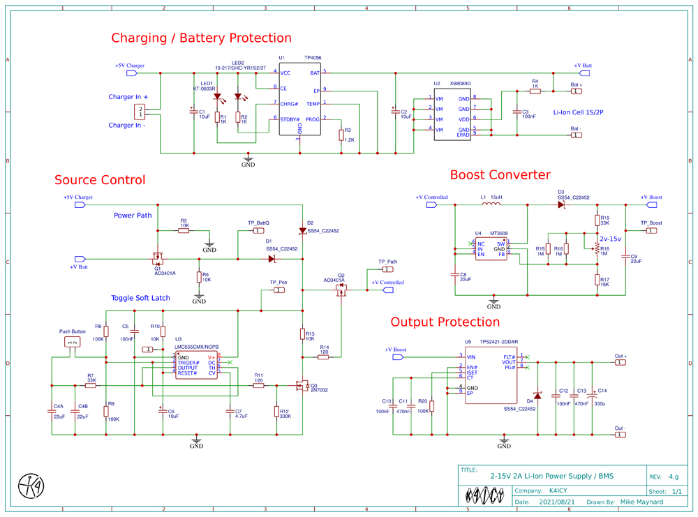 Stage 1: Charging Battery Protection [XB8089D] The purpose of this IC is to prevent overcharging, overdischarging, overcurrent, load short circuit protection and etc.. If any of these conditions exist and a threat to the battery is presented, the GND line (-) from the battery is severed until ideal conditions are met again. The parameters of this device are not user settable but other various packages are produced to address specific needs including higher current handling and telemetry. Li-Ion/Li-Po Charge Controller [TP4056-42] This IC controls the charging power presented to the battery. It senses the batteries State of Charge and provides feed power based on an established lithium battery charging method and detects when charging is complete. The resistor at the PROG pin sets charge current. It's advisable not to set this factor over that which will exceed 0.5 of the battery's "C" rating without inclusion of a thermocouple (and associated resistor network) at pin 1 of this device (*see spec sheet). [Version 2 - Revision 6.i] An additional resistor with in-series solder jumper allows for charge current of 1A (bridge jumper.) Two LEDs indicate charging status, one for "charge" and the other for "standby" and these lines can also be used to provide status to any microcontroller. Both may light simultaneously when the battery is not present, damaged or disabled which can denote a serious fault. [Version 2 - Revision 6.i] Exterior header pins are provided to allow for a single chassis mounted RGB LED or set of color-indicated LED's. Stage 2: Power Path [on Version 2 - Revision 6.i] Toggle Soft Latch using 74VHC74 D-Type Flip-Flop and SN74LVC2G14D dual Schmitt Inverter At the push of a button (referenced to ground,) this divide-by-2 circuit is configured to toggle its output to control a p-channel mosfet [AO3401A] (via N-type mosfet] to allow power from the battery or external source to reach the boost converter. An option to clear the flip-flop, subsequently turning off the BMS power to the host device, can be done via any external logic device including the host uC. Power from the external wall source, primarily intended for charging, is first routed via Schottky diode [SS54] and a second back-to-back set of mosfet's (bidirectional switch) will disengage the battery which is currently being charged from providing power to the host device when external charging power is present, preventing the battery from both trying to charge and discharge, which obviously undesirable. Stage 2: Power Path [on Version 0-1 - Revision (to) 4.g] Toggle Soft Latch using a 555 Timer [LMC555CMX/NOPB] At the push of a button, a 555 is configured to toggle its output to control a p-channel mosfet [AO3401A] to allow power from the battery or external source to reach the boost converter. Power from the external wall source, primarily intended for charging, is first routed via Schottky diode [SS54] and a second mosfet will disengage the battery which is currently being charged from providing power to the host device when external charging power is present, preventing the battery from both trying to charge and discharge, which obviously undesirable. As of future revisions, this optional was updated due to increased current draw from the boost regulator on the battery. This should not be as much of an issue for larger packs. Stage 3: Boost Converter DC-DC Switching Step-Up Converter [MT3608] This device uses a bypass inductor and diode to take the input voltage from the Power Path stage which has been modulated at 1.2Mhz and produces a desired output voltage which is set by an external resistor network for feedback. The input capacitor should be as physically close to the IC package as possible and the specs of the inductor should be able to handle twice that of the desired output current. Since each power source is subject to a voltage drop through their respective routing diode, boosting each source yields a reliable minimal voltage to the host device. A voltage drop on the battery will cause more current to be consumed from as the boost converter compensates to maintain its output. As of this posting, my design is not optimally efficient. Stage 4: Outgoing Protection The [TPS2421-2DDAR] Hot Swap Protection Module This IC is an added layer of protection for both the BMS as well as the host device. For most run of the mill Arduino projects, I wouldn't be concerned with adding this measure of protection, but experience with my Columns game project has shown that I better not take chances with an LED array that can swamp 3 amps continuous if the AVR chip is having a bad day. All in all, this package intelligently protecting against current inrush spikes and faults from the host device which could pose a problem for the booster or charging circuits. Additional filtering is also provided. It is also advised to add an additional protection of a fuse. Current Known Issues [for Version 1 - Revision 4.g Board]: [C6] on the Control Voltage pin (5) of the 555 IC causes power to be interrupted briefly when unplugging the charging source, but without this cap, the BMS has problems starting up and will arbitrarily shut off when rapid current needs are presented. This should not be an issue with the logic-latch version of this circuit [next major iteration]. Using a thermocouple resistor on the charging IC is strongly recommended. This is only used during charging and is designed to pull the battery out of circuit if heating is an issue to mitigate the possibility of exothermic runaway. Remaining Tests and Determinations [for Version 2 - Revision 6.i Board]: The use of an oscilloscope (I do not yet own) to collect data on present waveforms and indication of critical operations such as EMI and state-change ramps. An output current allowance graph for the full voltage adjustment range. Testing of other key Li-Ion/Li-Poly battery charging/use safety implementations as well as host device protections. Testing of microcontroller shut-down feature. 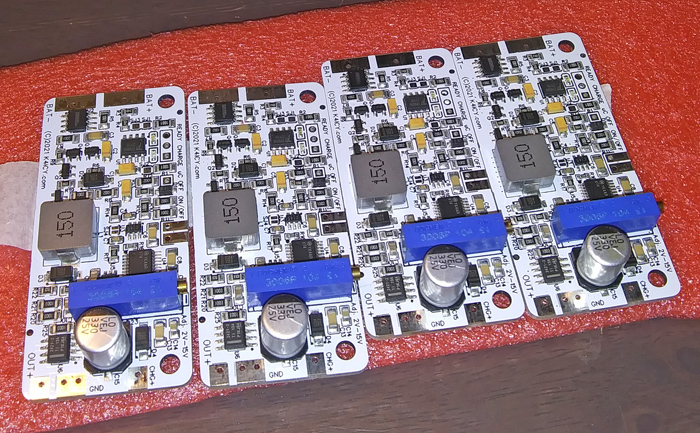 Here are four of the five beautifully produced populated BMS boards made by JLCPCB's SMT Service. MANUFACTURING FILES:::: The reason for me taking this small project on was out of necessity and at first I could not readily find any module or circuit design that handled everything I required, just pieces here and there. I needed a safe way to charge 18650 cells in a 1S format and there needed to be a simple but reliable output that could be switched on and off via a simple button, plus, I needed a BMS that could be integrated into any small project and also be repeatable. I have no intention to sell kits or completed boards but provide a working circuit and parts sources to you so that you can improve upon them and glean the best of any provided solution for your own use. This circuit [in whole] is protected by copyright but if you wish to manufacture and sell this circuit for yourself, I generally will have no problem with you doing so with the stipulation that I cannot be held liable for any unintended operation or accident. I suggest using JLCPCB to produce these boards for you, that is, if you wish to forgo any cheaper alternative. Bare PCB's are $2 a piece and will be at your door in a week. These parts are also extremely cheap, so if you have the setup and time and SMD mounting skills to build your own, you could probably make a board for $10 if you secure the parts. To have their SMD/SMT service mill the PCB's and Pick-and-Place the surface mount components for you, a 5 board run will give you a per-product cost in the ball park of $15. The "Extended" parts, especially some of the more specialized parts will hit the bank quick if you're no careful. Some parts have minimum orders on top of higher prices. The entire point to having a custom PCB made is to cater it to YOUR design specs and desired features. I plan on making the EasyEDA Project Open Source, only when I have fixed a few bugs, but I highly suggest only using my design as a template and make your tweaks and ordering with your own creation. I cannot guarantee operation of your build , of course. Files for Version 2 - Revision 6.i Board: Schematic_Li-Ion-Power-Supply-BMS-V2_R6i_2021-09-23.pdf Gerber_PCB_Li-Ion Power Supply_BMS_V2_R6i_2021-09-23.zip BOM_PCB_Li-Ion Power Supply_BMS_V2_R6i_2021-09-23.csv PickAndPlace_PCB_Li-Ion Power Supply_BMS_V2_R6i_2021-09-23.csv Files for Version 1 - Revision 4.g Board: Schematic_Li-Ion_Power_Supply_BMS_4g_2021-08-23.pdf Gerber_PCB_Li-Ion_Power_Supply_BMS_4g_2021-08-23.zip BOM_PCB_Li-Ion_Power_Supply_BMS_4g_2021-08-23.csv PickAndPlace_PCB_Li-Ion_Power_Supply_BMS_4g_2021-08-23.csv Contact me at mikek4icy@gmail.com 73 DE MIKE K4ICY Updated
09/23/21
|