| Weekend
Radio Projects you can build -
Hosted by:
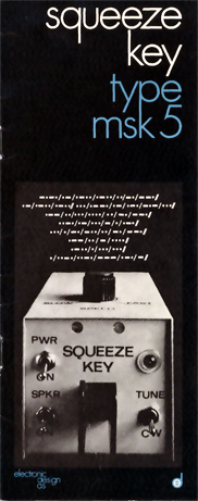
Mike Maynard, K4ICY CLICK HERE for More K4ICY Electronics Projects tutorials including the Minty Keyer... NM7T "OZ" CW Keying Mode Adapter CW Squeeze Keyer Input Adapter based on the MSK-5 by Brian Kelley, NM7T .
OZ Mode Adapter SCHEMATIC: 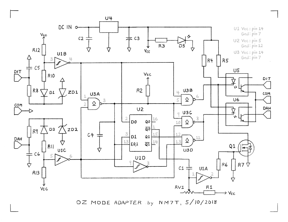 . PARTS LIST: (Updated 05/10/2018) U1 • 74HC14 Hex Inverting Schmitt Trigger U2 • 74HC75 (or 74HC375) Quad Bistable Transparent Latch (Please note manufacture's pinout specs for equivalents!) U3 • 74HC03 Quad 2-Input NAND Gates with Open-Drain Outputs U4 • 78L05 +5 Volt Regulator U5, 6 • 4N35 (or equivalent) Optocoupler Q1 • 2N7000 N-Channel MOSFET D1, 2 • 1N4148 Small Signal Fast Switching Diode D3 • LED, 3mm (Optional) ZD1, 2 • 1N5231B 5.1 Volt Zener Diode C1 • 0.1 μF C2 • 0.1 - 0.47 μF C3 • 10 μF to 100 μF electrolytic C4 • 0.22 - 1 μF metallized polyester C5, 6 • 10 nF ceramic type Note: Capacitors C1 and C4 should have low dielectric absorption, ie: metallized polyester or metallized polypropylene film dielectric types. R1 • 15K Ohm R2, 6 • 10K Ohm R3 • 330 to 680 Ohm R4, 5 • 680 Ohm R7 • 1.0 M Ohm R8 - 11 • 1.2 K Ohm R12 - 13 • 33 K Ohm RV1 • 100 K Ohm Linear Potentiometer or Trimmer Note: All resistors are 1/4 Watt with 10% tolerance unless otherwise noted. . 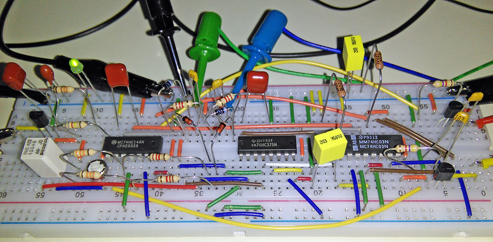 Shown here is an earlier revision of the NM7T OZ Mode Adapter::: Part count is low enough that a mint tin may be considered for housing this project if built compactly. . Circuit Description
I will refer to the MSK-5 in this documentation
even
though it applies to the MSK-4 Squeeze Key also. The MSK-5's
main
feature was it's "single-dot memory and injection" system.
The
NM7T OZ mode adapter provides the "single-dot (pulse) injection" while
the host keyer provides the "dot memory." Although dash
memory is
not required on the host keyer used with my adapter, it will add the
ability to "squeeze" an "A" just as Mode B allows if you release both
levers within the first element (dot).
.The OZ mode adapter now has an optional "Squeeze eXtender" (SX) circuit. This circuit uses the keyline or sidetone signal from the host keyer to basically hold the latch of U2A closed after one or both levers are released. This has the effect of extending a squeeze until the end of the current element. The SX circuit operation is explained in detail in the 'Squeeze eXtender' section. When the OZ adapter is used without the SX option, it requires a bit more practice to send certain characters with the 'squeeze' method. These characters all end with a dash or a dash-dot element-sequence. For example, when sending the letters "K" or "C" (using the 'squeeze' method) the sequence in which you release the squeeze (all on the second dash) must be practiced. By releasing the dot lever before the dash lever, a "K" is sent. But if you releasing the dash lever before the dot lever, a "C" is sent. You may be thinking "how can you squeeze an 'A' using the adapter when the host keyer is running mode B?" The adapter does this by simply cutting off the squeeze at (nearly) the instant the dash lever closes. Note: The dash lever must close within the period of the [dot element plus inter-element space] sent by the host keyer AND upon releasing the "A squeeze" (which must be done within the period of the [dash element] sent by the host) the dot lever must be released before the dash. If an "A" is squeezed, gate U3A cuts off the the squeeze by closing gate U3B. This gate can only operate (go LOW) if the output of U3A is HIGH. At the instant the dash lever closes, the "squeeze" (as we call it) begins, but there is a short delay of ~150 μs between the output of U1C going HIGH and the output of U3A going LOW. When the output of U3A is LOW, the latch enable (E0,1) input of U2 is also LOW. So prior to U3A going LOW, the latch is in it's transparent mode. At (nearly) the instant U3A goes LOW, U2 latches the state of it's outputs. Prior to the start of the "squeeze", the dot signal (logic level) passes through U3B to optocoupler U5 and out to the host keyer. With U2 in it's transparent mode, the closed dot lever sets not_Q0 of U2 LOW. This LOW on not_Q0 initiates the dot pulse which also goes out to the host keyer. (I will cover this section of the adapter further down.) Before the dash lever closes, the state of U2's Q1 output is LOW. But with the delay caused by U3A and C4, output Q1 is latched HIGH at (nearly) the instant the dash lever closes. So with Q1 latched HIGH, only the dash signal is seen by the host keyer even though both levers of the paddle are closed. So as long as you have made "the squeeze" quickly AND released the levers in the right sequence, you can squeeze an "A". There is no advantage in having the host operate in Mode A as long as Mode B operates with 100% dot and dash memory. 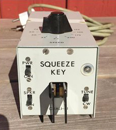 . The Single Dot (Pulse) Injection Circuit
When the not_Q0 of U2 goes LOW, the
surge in
current charging C1 causes a momentary voltage drop across RV1 + R1.
The Schmitt trigger inverter, U1A, squares-up this pulse.
MOSFET
Q1 pulses the LED in optocoupler U5. Resistor R7 protects the
MOSFET gate from damage when U1 is out of the circuit.
C1 should
have very low dielectric absorption for stable pulse generation.
This is why a metallized polypropylene capacitor should be
used
for C1. There are only two paddle states in which a dot pulse
is
fired. One is when the dash lever is open and the dot lever
is
pressed. The other is when the dash lever is already closed
and
the dot lever is pressed.
Note: A dot pulse is NOT generated on a (dash first) release of a squeeze. U3B passes this dot signal. The pulse width is adjustable from approx. 1 to 9 ms. When RV1 is set to minimum resistance, the pulse width is ~1 ms. If your host keyer is not recognizing the injected dot pulse, try increasing the value of R1. For comparison, at 22 WPM the length of a dot (less inter-element space) is ~54 ms. . The "Squeeze Debouncer" The function of C4 is threefold:
1) It increases the propagation time of
U3A when the output switches from HIGH to LOW.
This
provides a little extra time for a lever closure to reach the
Qn
output of U2 before being latched-in.
2) It prevents the latch enable input of U2 from bouncing between LOW and HIGH. Hence the name... "Squeeze Debouncer". 3) It gives you a few milliseconds of freedom in releasing both levers at the same time within an element. For example, if you release a squeeze on the second dash of a "K" with the dot lever let off last, you won't get bitten with a "C" if you released the dash lever a few milliseconds prior to the dot lever being released. This window of freedom is ~7 ms with a 1uF cap for C4. Note: If you want an adjustable window of freedom, add a 50K Ohm linear pot in series with R2. This will allow you to set the window as wide as ~41 ms. . The Simul-Squeeze Test
If you want to verify your keyer has
100% dot and
dash memory on modes A, B, and Ultimatic, perform the following steps:
1. Disconnect the paddle from the cable going to the keyer (or build a test cable). Twist the dit and dah leads together so you can simulate both levers closing at exactly the same time. 2. Set your keyer to the lowest possible speed, like 5 WPM. 3. Now, emulate a "Simlu-Squeeze" by quickly touching the twisted leads to ground. You should hear just an "A" or an "N". NO "ET", "TE", or mix of A's and N's. If you DON'T hear consistent A's or N's on each touch, the mode does not have 100% dot and dash memory. If the keyer gives an erratic response, try the following: Use U5 and U6 to isolate the dit and dah paddle lines instead of twisting the leads on your paddle cable. To do this, first add a test point terminal at the cathode of U5 and U6 (pin 2 on the 4N35). Then connect a wire (or "SS Test" switch) between the two terminals. Set the host keyer to the lowest speed and connect your paddle to the input of the OZ adapter. It does not matter which lever you tap since either will simulate a simul-squeeze! Most keyers will give an "A" response to the Simul-Squeeze test. This is because the dot element pulse is (usually) the keyer's timing reference for generating a dash element. If a keyer responds with an "N" instead of an "A", that is perfectly acceptable since either response will only occur if the levers close within 50 or so microseconds of each other. . OZ Adapter Technical Specifications Supply Voltage: Approx. 8 to 18 Volts DC when using a 78L05 or equivalent 5V regulator. Note:
If you plan to use a LDO 5V regulator, be sure the output capacitor
(Cout) has at least the minimum required capacitance AND it's
ESR is
within the range specified in the datasheet. Polarity Protection - Consider
"goof-proofing" your build by
using a polarity protection diode such as a 1N4001 at [DC IN].
Current Consumption (with R3 = 330 Ohms) 12.1 mA (idle) 17.5 mA (one lever closed) 18.1 mA (both levers closed) Note:
To lower current consumption, leave LED D3 out of the circuit
or add
a switch to disable it. If you plan to dedicate the
adapter circuit to
your keyer,
you can reduced the current consumption even more by
leaving out
the optocouplers. Be sure to ground the unused inputs of U1 and U2.
Paddle Voltage: ~4.3 Volts Paddle Current: ~130 μA each Optocoupler output sink current: ~5 mA max. Note:
Paddle inputs are protected from ESD, RFI and any accidental
connection
of DC supply voltages. Capacitors C5 and C6 along
with the hysteresis
provided by U1B and U1C eliminate any paddle contact
bounce. U1 and U2 - Consider adding decoupling caps (0.1 μF)
between the Vcc and Gnd pins.
.MORE... . Mode A and B Variants
Some keyers don't have dot and dash
memory when
operating in mode A. Without dot memory, the host keyer will usually
miss the ~5 ms dot pulse
when an "N", "K" or "Y" is squeezed at low speeds. Some
keyers
(notably Logikey's V0 mode) have a modified mode B. V0 mode disables
the dot memory during the first third of the dash. This
lowers
the chance of accidentally sending an "R" when an "A" is squeezed. But
if used as the host keyer, it can cause an "M" to be sent when trying
to squeeze a "K".
The K1EL keyers have an adjustable memory "window" when operating in mode B. It works like V0 mode in the default setting. Having the OZ mode adapter's dot injection "window" reduced may cause errors in your sending. For example, you might hear a "T" go out when trying to squeeze an "N". . Ultimatic Mode Variants
The original Ultimatic keyer was built
by John
Kaye, W6SRY, in 1953. It used a single-lever paddle. In 1955, John
created the twin-paddle Ultimatic
keyer which ALSO had dot and dash memory. I bet you know were I'm
headed with this. Most
modern keyers include an Ultimatic mode, but it
may be really "sub-ultimate" if it does not include dot and dash
memory.
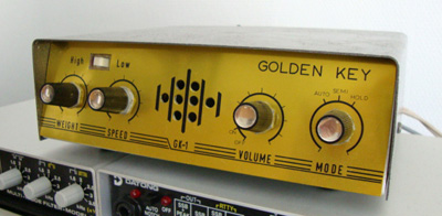
.Then there are dot preferred and dash preferred Ultimatic modes. If dot preferred is used, you will have a hard time trying to insert a dash while holding the dot lever closed. With dash preferred, you will be lucky if you can insert a single dot! Obviously, these two modes must not be set on the host keyer. Another variant of Ultimatic mode adds an opposite element when a "squeeze" is released. Think of Ultimatic mode w/dot and dash memory mixed with the added trailing element of mode B. I would call it "Ultimatic-B" mode but the keyer that has it just calls it Ultimatic mode. In the next section you will read more about the dot preferred mode which is overlooked by many keyer manufactures of today. The dash preferred mode was less popular than the dot preferred, but it was around long before mode A and B arrived in the 70's. You may not realize it, but a certain keyer was based on an old dash preferred mode keyer. Can you guess what that certain keyer is? OK, you guessed right. But can you guess which host keyer mode (or modes) makes the OZ mode adapter operate like a dash preferred mode keyer? The GK-1 Golden Key Keyer Notes: 1) EW-Line (Helsinki, Finland) built the GK-1. EW-Line was founded by Reijo R. Laine, OH2EW. He was a pioneer in component and HiFi equipment selling in Helsinki in the 60's and 70's. The GK-1 Golden Key was produced from 1967 to 1974. The GK-1 at the the Radio Museum. https://www.radiomuseum.org/r/ewline_golden_key_electronic_ke.html 2) The Autronic MK-1 electronic keyer page at the Radio Museum. https://www.radiomuseum.org/r/electrophy_autronic_keyer.html In a email, OH6NT Thomas wrote... "The Autronic schematic was copied in 1965 by OH2EW Reijo and OH2QV Anssi." OH6NT has a very large collection of keys and paddles (and some keyers) at: http://www.tronico.fi/OH6NT/keys.htm Reijo owned the Hi-Fi import company EW-line. In 1967 the first Golden Key (kit) was sold. EW-line later came out with the GK-1 Mk II. By coincidence, my first paddle was an Autronic. As I recall, it was about $80 in late 1967. (bk) 3) If the GK-1 Golden Key circuit was copied from the Autronic MK-1, then the Autronic operated in dot preferred Ultimatic mode. 4) The Autronic paddle and keyer was first advertised in the June, 1960 issue of QST. http://www.qsl.net/n6tt/keyerpad.html#auto 5) https://web.archive.org/web/20221201035702/http://www.mattikaki.fi/hobbies/1971.htm 6) The JUMA-KEYER1 webpage. (Note: Mode A does not have dot & dash memory) http://www.jumaradio.com/juma-keyer1/ 7) The Simple CW Keyer (elbug) of Matti Hohtola, OH7SV. This keyer has the same keying logic as the GK-1 Golden Key. https://web.archive.org/web/20220904192135/http://www.saunalahti.fi/hohtola/ham/elbug/oh7sv-elbug.htm Email: matti.hohtola@saunalahti.fi 8) https://www.k7mem.com/Keyer_Simple.html . 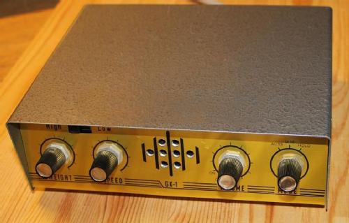 The Finnish GK-1 The Finnish GK-1. HOW TO USE OZ MODE: OZ Mode is pretty easy to learn, and if you know how to use Ultimatic Mode then you are almost there. We must assume here that you already own a dual-lever paddle of some sort and have general CW experience. Click image below for full-sized version: 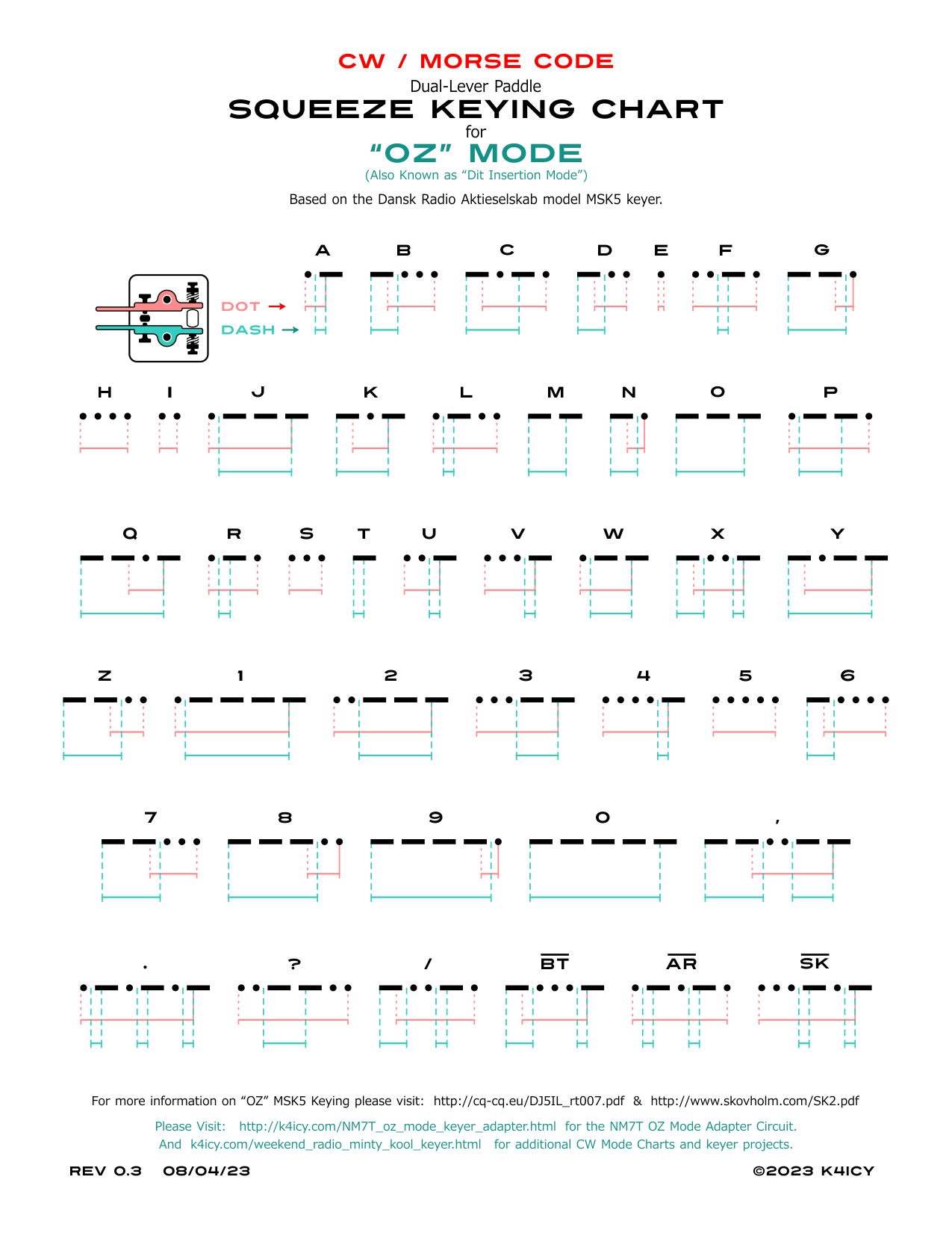 Click here for the PDF: CW_Dual_Paddle_Squeeze_Keying_Chart_for_MSK5_OZ_Mode.pdf . Edited:
08/04/23
|
