 Arduino Projects By Mike, K4ICY Arduino Projects By Mike, K4ICY Weekend Radio Click Here for More Electronics Projects and Tutorials By Mike Maynard, K4ICY . HOW TO PROGRAM AN ATtiny85 FROM ARDUINO IDE . And other Tiny AVR Microcontroller Varieties . • ATTiny25/45/85 Pinout
• Programming
with a USBasp Programmer • Make a USB direct-programmable ATTiny85 (Digispark) • Get the ATTiny talking to the Serial Monitor - using only 1 pin
• Building
a Fuse Setter for the ATtiny and its
implementation - Get 6 I/O pins from your ATTiny85! • Pitfalls and workarounds - including no UART, the Tiny's ADC noise issue and others
• Enhancing
ATTiny85 Coding with Low-Level Commands and Bitwise Operations for More
Space and Speed .
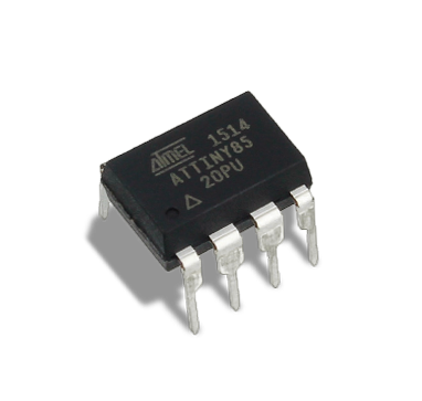
The ATtiny85 is a small 8-pin AVR
microcontroller which is the much smaller cousin to the Arduino's
ATmega328p. The 'Tiny' comes with a lesser fraction of the
features of the larger more popular 328p but is a perfect solution for
the
majority of "maker" DIY homebrew projects which may often not
require more than 5 or 6 I/O pins due to being smaller and simpler.
The ATtiny85 and others of the ATTiny series are part of a
much
larger family of "AVR's". It
was released back in 2005, but because of its low price point and
maker- friendly 8-pin DIP(DIL) through-hole package, it is still in
production
by Microchip today. There are still
large quantities available from vendors including Digi-Key despite the
chip shortages of the last few years, and is basically the go-to for
DIY maker
projects. SMD
options in 8-pin SOIC and 20-pad QFN/MLF are also available for more
professional prototypes and production turnkey products. This
page will use "ATTiny" and "ATTiny85" interchangeably and most of the
examples and features are compatible among different IC types.
Though there are some limitations and lack of certain
features to
be found in Arduino IDE (using an installed core,)
More
Here from Microchip . . Pinout for the ATTiny25, ATTiny45 and ATTiny85: . Source: https://github.com/SpenceKonde/ATTinyCore . (Click image for large
version)
Installing an Arduino IDE Boards Manager Core for the
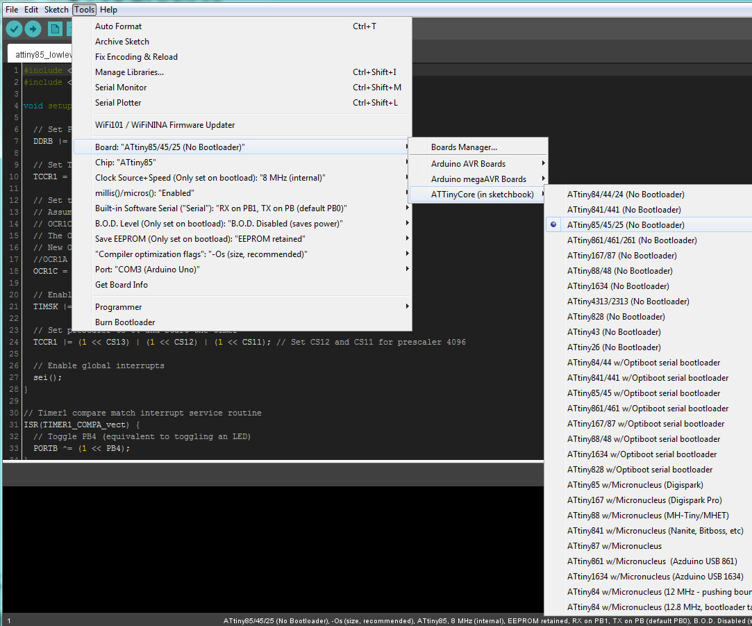
ATTiny's . The Arduino IDE out of the box doesn't come with any support for the popular ATTiny series of AVR, which is odd that is so, but with a few steps you should be up and running in no time with a vast selection of ATTiny IC types and a ton of fine-tuning options to choose from. There are a couple of cores available on the web if you search hard enough, but the most recognized core is maintained by Spence Konde and you will find a selection of his core, ongoing updates and user comments at his GitHub site: https://github.com/SpenceKonde He's done an amazing job and if you find his core useful for your ATTiny adventures, please consider a contribution. Since installing anything within the Arduino IDE can be daunting, I'd like to break this down step by step. You'll have to forgive me if you get stuck or anything doesn't work, and if so, there are some pretty good communities out there who deal with this stuff. Arduino version 1.8.13 or new is recommended. . Step 1: Installing The Core . METHOD 1 - Automatic Installation The Spence Konde ATTinyCore can be installed automatically to update the Boards Manager. http://drazzy.com/package_drazzy.com_index.jsona. Go to the menu: File -> Preferences (on a PC), or Arduino -> Preferences (on a Mac), enter the above URL in "Additional Boards Manager URLs". b. Go to the menu: Tools -> Boards -> Boards Manager... c. Search for, and Select "ATTinyCore by Spence Konde" then click "Install". You may get the error message: "Error downloading http://drazzy.com/package_drazzy.com_index.json" when opening the Boards Manager. It may be because the author or host site hasn't renewed the certificates, or for some other reason. It seems to be doing this on some machines but not others. If so, you'll have to try the second method. . .... 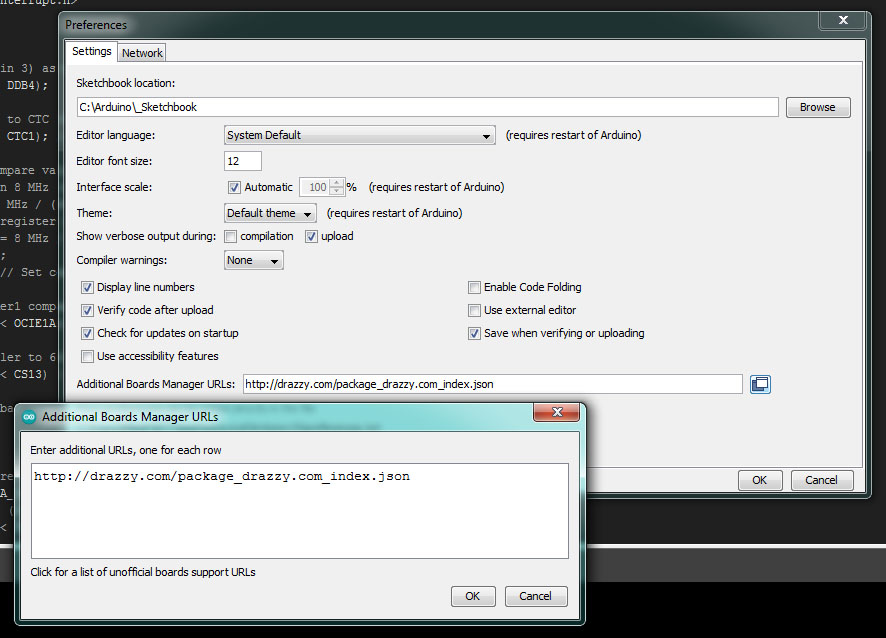 . METHOD 2 - Manual Installation It's not that hard to do - you're just downloading and unpacking a ZIP file and putting it in a special Arduino folder. a. Download the ZIP file from Spence Konde's GitHub page: Click on the green <> Code button and choose "Download ZIP" from its drop-down menu. b. Locate your Arduino IDE Sketchbook folder. To find this go to the menu: File -> Preferences (on a PC), or Arduino -> Preferences (on a Mac), and use your File Explorer to navigate to the listed folder under "Sketchbook location:". c. If there is not a folder inside of your Sketchbook folder named "hardware", then create one! This is where user-created boards would go. d. Inside of your sketchbook/hardware folder, place and unpack the contents of the downloaded ZIP file. Make sure that only the main folder named "ATTinyCore-2.0.0" (or whatever version) containing its files is what's sitting there inside the hardware folder as sometimes ZIP files nest folders within extra folders. e. Re-launch Arduino IDE and now "ATTinyCore (in sketchbook)" should be a new sub-menu under Tools -> Board: I would recommend downloading the ZIP and keeping it handy JUST IN CASE something happens to the GitHub post or the .json link! Also, download a couple of the prior release versions if possible to work around any possible compatibility conflicts.. . Alternatively, you can also try the ATTiny core by David A. Mellis. Here is the Boards Manager URL .json: https://raw.githubusercontent.com/damellis/attiny/ide-1.6.x-boards-manager/package_damellis_attiny_index.json Now you should be ready to set up the programming interface... .
Setting Up a Programming Interface for the ATTiny . Step 2: Prepare the "Programmer" Arduino Uno R3 a. Connect the Arduino Uno R3 (Arduino Nano, or etc.) to your computer via USB.. b. In Arduino IDE, select "Arduino Uno" (or other board such as the Nano) from the menu at: Tools -> Board: -> Arduino AVR Boards ->. c. Select the appropriate serial port in the Tools menu. d. In Arduino IDE choose "Arduino as ISP" (In-System Programmer) under the Tools -> Programmer: menu. [Do NOT choose the "ArduinoISP" option as that is a specific non-related Arduino product] e. Open the "ArduinoISP" Example sketch in your IDE and UPLOAD this to your Arduino. [Do NOT install the 10uF capitor to Reset+GND on the Uno yet until the sketch is uploaded!] You should see the "Heartbeat" LED fading in and out, indicating that the programmer sketch is running. . .... 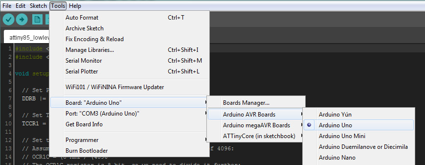 . .... 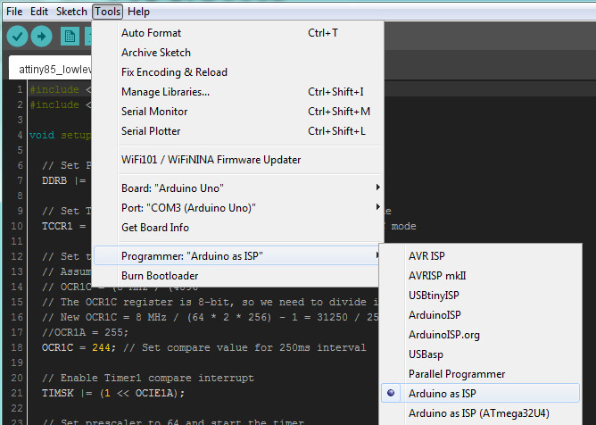 . Step 3: Connect the ATTiny to the Programmer Connect the Arduino Uno R3 (Nano, etc.) to the ATTiny85 IC as follows: (Will also work for ATtiny13, ATtiny24, ATtiny44, ATtiny84, ATtiny25 and ATtiny45.) Arduino Uno 5V to ATTiny85 VCC [IC pin 8] Arduino Uno GND to ATTiny85 GND [IC pin 4] Arduino Uno 10 (SS) to ATTiny85 RESET [IC pin 1] Arduino Uno 11 (MOSI) to ATTiny85 MOSI [IC pin 5 / PB0, PCINT0, SDA] Arduino Uno 12 (MISO) to ATTiny85 MISO [IC pin 6 / PB1, PCINT1] Arduino Uno 13 (SCK) to ATTiny85 SCK [IC pin 7 / PB2, PCINT2, SCL] Wire as shown: (Click image to enlarge) . ..... 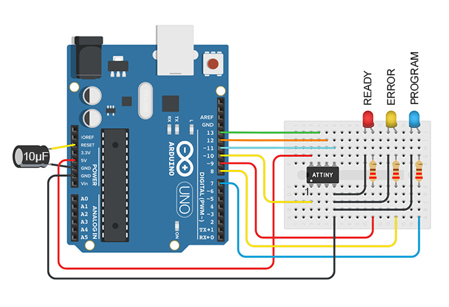 . .
Burning the Bootloader and Uploading a Sketch . Step 4: Configure The
Core .... .
Step 5: Burn
the Bootloader
a.
Select "Arduino as ISP"
from the Tools ->
menu.
a.
Prepare your desired sketch in the Arduino IDE. .
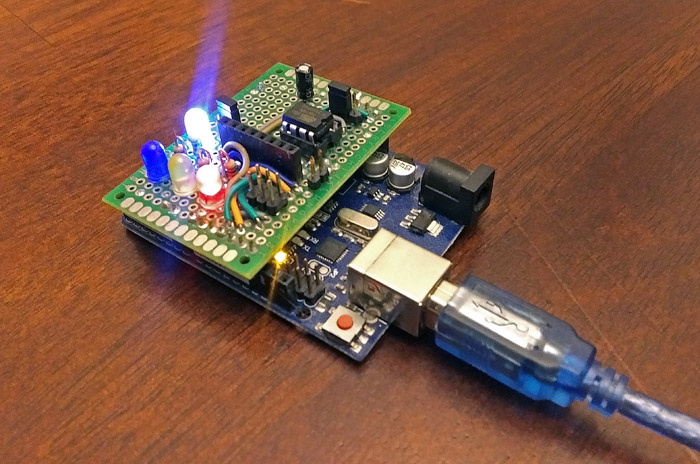
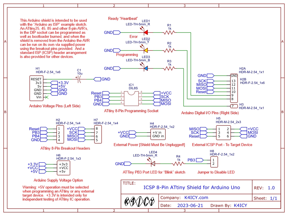
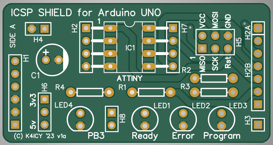
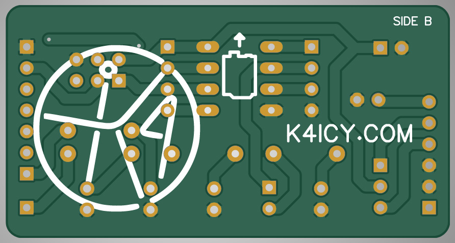
An ATTiny ISP Programming Shield for the Arduino Uno .
Shown here is a homebrew ISP Programming Shield prototype
for the Arduino Uno.
[I'll be having a PCB version made by JLCPCB (Files
Below) and I'll post pics and results here!] . . . Here are some additional Programming Shield ideas: .
Programming an Attiny+Homemade Arduino Shield
[GreatScott!]
.
Making the ATtiny85 Easier to Program
[Ralph S. Bacon #84]
. .
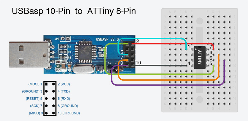
Programming the ATTiny with a USBasp AVR Programmer . When seriously working with ATTiny85's and any other AVR-type microcontrollers, having a reliable method for programming and bootloader burning is essential. The USBasp programmer is a popular choice for many makers and professionals as it's cheap, simple, versatile and eliminates the need to questionably wire up a sacrificed Arduino. This section will describe the setup and functionality of a USBasp programmer and explain why it's an excellent tool for programming the ATTiny85. . .. What is a USBasp Programmer? The USBasp is an open-source USB in-system programmer (ISP) for Atmel AVR microcontrollers. [The "asp" in "USBasp" stands for "AVR Serial Programmer."] Developed by Thomas Fischl, [more at fischl.de] it allows users to program AVR microcontrollers through a USB connection, eliminating the need for a parallel or serial port programmer, and is functional version of the extra microcontroller IC on an Arduino board. The USBasp is compatible with various (Microchip) AVR microcontrollers, including the ATTiny85, and supports standard programming software like AVRDUDE, making it a good tool for embedded development beyond the Arduino UNO. The following are some advantages to choosing this programmer: . . Why Use a USBasp Programmer? Direct Programming Capability: The USBasp programmer directly interfaces with the ATTiny85 through its ISP (a.k.a. ICSP In-Circuit Serial Programming) pins. This allows for easy and reliable uploading of sketches and firmware without the need for an additional bootloader or complex setup. For users who want to program multiple devices quickly, the USBasp is straightforward. Bootloader Burning: If you need to burn a bootloader onto an ATTiny85, the USBasp can handle this task quickly. Burning a bootloader is necessary when starting off with a fresh microcontroller chip, preparing one for use in certain projects or when switching between different programming methods (ie.,using an Arduino IDE or direct ISP programming.) The USBasp programmer simplifies this process, even making it accessible to those who are new to non-Arduino microcontroller programming. Compatibility and Support: The USBasp is widely supported across various operating systems and works seamlessly with AVRDUDE, a powerful command-line tool for programming AVR microcontrollers. This broad compatibility ensures that you can use the USBasp with your preferred development environment, whether you're on Windows, macOS, or Linux, or whether you're using Microchip Studio or Arduino IDE. Affordability and Availability: The USBasp programmers are cheap and plentiful! Generally made in China, and found online from many vendors hosting on store sites including Amazon, eBay, AliExpress and more, can be found for only $2 to $9 a piece. They're an affordable solution, making it an attractive option for hobbyists and educators who need to equip their labs with a quick and simple programming tool without breaking the budget. You may even be able to find them at Micro Center or other local electronics stores, and its certainly possible to build your own. . .... 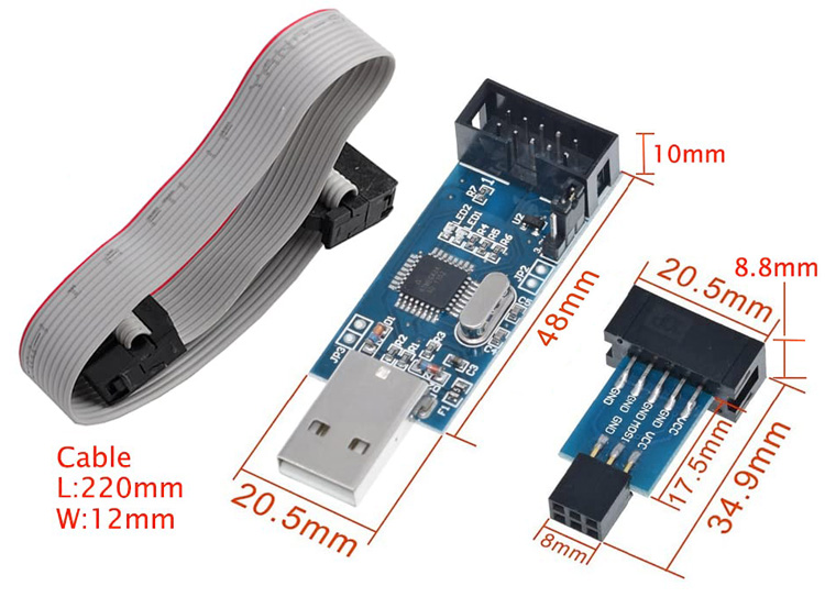 . Keep in mind this incredible contrast, that before the USBasp and Arduino, if you wished to program an AVR microcontroller, you would've had to shell out hundreds, if not thousands of U$D just to upload sketches! Currently, at the high-end, there's the Microchip MPLAB ICE 4 In-Circuit Emulator which will set you back $1,000 - $2,000 for the base model and up to $5,000+ to get all the bells and whistles. Though, the MPLAB ICE is intended for precises mission-critical microcontroller development by electrical engineers, it includes debugging and simulation, and also works with PIC, dsPIC, and SAM devices as well as AVR, so the price reflects its abilities. Firmware Flexibility: One of the strengths of the USBasp is its Open-Source nature, which allows for firmware updates and modifications. This means that the programmer can be kept up-to-date with the latest features and improvements, ensuring the possibility of continued compatibility with new microcontrollers and programming requirements. The caveat to this is that development has been slow the last few years and though, Arduino IDE still has the option to program with the USBasp, they don't provide any drivers* (more on that below.) Small Power Supply Source: The USBasp can power the target microcontroller during programming without the need for an external power supply, which is a particularly useful feature for small, low-power devices like the ATTiny85, simplifying the programming setup and reducing the number of components needed. You should be able to make a small ATTiny break-out board with an IC socket, an ISP header and a test LED requiring no solderless breadboards, DuPont cables or other power supplies. The USBasp programmer is a must-have tool for your Arduino/microcontroller kit (and gives you "street cred" points.) It's a convenient for working with ATTiny's and its ability to program directly through ICSP and burn bootloaders is just as useful for both beginners and advanced users. Why, you can even program your Arduino UNO! . . Installing Your USBasp Programmer: If you're using a Linux-based system or MacOS then there's no need to find a driver, just plug it in and it should work. It's a different story for Windows users as you will need to install a driver! Windows will search for one but will most likely not have any success. As a base requirement, first, your USBasp should be using ether an ATmega8, ATmega88 or any other compatible mcu chip, and second, you'll be out of luck if you're not using Windows 7 or later as Windows XP, Vista and any previous OS is not supported. Make sure to watch the provided YouTube videos for deeper tutorials. To install the USBasp driver: Go to https://zadig.akeo.ie/ and download zadig-2.9.exe (2.9 is the latest as of this writing.) Zadig is a Windows application that installs generic USB drivers to help you access USB devices. Plug in your USBasp programmer into a USB port and then run the Zadig application and select "USBasp" under the Device drop-down list. You may have to click on the menu: Options and check "List All Devices", then choose USBasp from the drop-down list. If your USBasp is the only USB device connected without a driver then it may automatically present it at once. . ....  . Next to "Driver" you'll see two field boxes: [ None (or previously installed driver) ] => [ (Suggested Driver) ] The Suggested Driver field (on the right) will give you the option to choose from five or six various drivers. Many users say that either WinUSB or LibUSB will work, but you may have to install [or Re-Install] each one on the list until you see no conflict issue inside your Windows Device Manager, or you are able to actually program with you USBasp. Click the [ Install ] (or Re-Install..) button to install the driver, and you should now be ready to program your ATTiny85 or other AVR microcontrollers. You should also be able to use any USB port as your PC will simply carry over the installed driver. For any issues concerning installation, please search for any good advice online or through YouTube. . And watch the helpful how-to guide "How to Use USBasp Programmer with Arduino Boards" by Zero Amps Electronics: .. .... . Firmware Update Instructions: Your USBasp programmer should work straight out of the wrapper on your ATTiny85's and ATmega328p's chips, but since most of these are made in China by sketchy outfits that may not care about selling up-to-date products, your USBasp's firmware will most likely be out of date. You'll know this right off when pploading a sketch in Arduino IDE and you get several errors from AVRDUDE telling you that, for one, the SCK speed cannot be set correctly, along with other issues. Updating the USBasp's firmware, or rather, the programming on the ATmega8x, will fix this and is a process we'll describe here. FIRST - You're going to need two USBasp programmers! I'm glad you read this part first before only ordering one. They're so inexpensive, you can sometimes find them in 2-packs for $10. [HERE] You'll be able to update the firmware on one USBasp by using another and then vice-versa. [You may be able to use an Arduino UNO set as ISP, but at this time I'm unsure of the right settings.] Here are the general steps: Download the Firmware Update: • Go to: https://www.fischl.de/usbasp/ and download: usbasp.2011-05-28.tar.gz • Unpack (twice with .gz and .tar) and get the file: usbasp.atmega8.2011-05-28.hex which will be inside of several folders. • Place this file in your C:/ root folder for convenience. Prepare the USBasp's: • Locate "J2" or "JP2" on the USBasp's. It's a psir of solder via holes generally located next to the voltage selection jumpers. Some manufacturers put one there, but if there are no header pins soldered to those holes you should do that yourself. Set the Target USBasp to Programming Mode: • Bridge the jumper (usually "J2" or "JP2") on the target USBasp that enables "self-programming." This usually connects the RESET pin to ground. .... 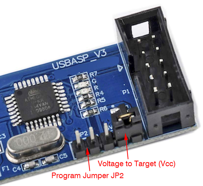 Connect the Programmers: • Plug the first USBasp (the programmer) into your computer's USB port. You may notice the LED(s) light on the programmer USBasp while it is not lit on the target USBasp. • Connect the second USBasp (the target) to the first one using the provided ribbon cable to bridge the two respective 10-pin the ICSP headers. Prepare the AVRDUDE Command: • Go to the Command Prompt and navigate to the directory containing avrdude.exe. In Command Promt, use CD (plus the directory) until you get to the folder where avrdude.exe is located. Most likely: C:\Program Files (x86)\Arduino\hardware\tools\avr\bin\ • But first, using File Explorer, copy the avrdude.conf file over from C:\Program Files (x86)\Arduino\hardware\tools\avr\etc\ to the adjacent ...bin\ folder so that avrdude.exe can find it when its command line is executed. • You will use AVRDUDE to upload the firmware to the Atmega8 on the USBasp. The basic syntax of the command is as follows: avrdude -c usbasp -p m8 -U flash:w:c:\usbasp.atmega8.2011-05-28.hex:i Here's a breakdown of each command line 'switch': -c usbasp: Tells AVRDUDE to use the USBasp programmer. -p m8: Specifies the target microcontroller, in this case, the Atmega8 on the target USBasp device. -U flash:w:c:\usbasp.atmega8.2011-05-28.hex:i: Tells AVRDUDE to write the specified firmware to the flash memory of the Atmega8. Replace "c:\usbasp.atmega8.2011-05-28.hex" with the path and name of you firmware file. Run the Command: • Type out this command line, or right-click and paste using your mouse and Enter it. AVRDUDE will provide output indicating whether the operation was successful or if there were errors. • If the process completes successfully, your target USBasp has been updated with the new firmware! Your may notice the LED(s) on the target USBasp now light up. Remove the Jumper, Switch and Repeat: • Once the update is complete, disconnect the USBasp programmer and remove the "self-programming" jumper from the target USBasp. • The target USBasp will now become the programmer and the programmer, the target. Place the jumper on the new target USBasp ("J2" of "JP2"). • Place the new programmer (old target) into the USB port keeping each USBasp device connected to each other via the programming ribbon cable. • Repeat the above steps from running the AVRDUDE command again. [Hint: press F3 to recall the previously entered command line.] Troubleshooting: Access Issues: If you're on a system that requires administrative privileges to access USB devices, you might need to run the command with "sudo" on Linux/macOS: sudo avrdude -c usbasp -p m8 -U flash:w:usbasp.atmega8.2023-02-28.hex:i USB Drivers: Ensure that the necessary USB drivers are installed (see above,) especially on Windows. This might involve installing the particular libusb driver for USBasp. Correct Firmware: Make sure the firmware file is compatible with the Atmega8 microcontroller on your USBasp programmer. Good luck! And watch the helpful how-to guide "How to Upgrade Firmware in USBasp Programmer" by Zero Amps Electronics: .. .... . . Wiring Up Your ATTiny85: If using the default 10-pin ICSP programming connector on the USBasp, seat your ATTiny85 in a solderless breadboard and use female/male DuPont jumper wires, connecting the following pins from the USBasp to the corresponding pins on the ATTiny85 as follows: .
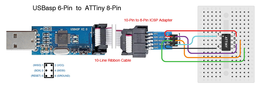
. If using the 10-pin to 6-pin ICSP adapter connected via the provided ribbon cable from the USBasp, seat your ATTiny85 in a solderless breadboard and use male/male DuPont jumper wires, connecting the following pins from the USBasp+ISP adapter socket to the corresponding pins on the ATTiny85 as follows: .
. Study these setup diagrams and carefully note markings on each device for correct orientation! NOTE: Make sure the ATTiny85 IC is properly seated in its socket or on the breadboard with CORRECT orientation - Pin 1 is always on the upper-left of the IC when looking down and often has a circle or divot next to it. There's also always a half-circle notch in the side denoting where Pin 1 will be to the left of it. Make very sure the orientation and pin locations of the programming sockets are correct as rotating them 180 degress may send VCC into Pin 7 of the Tiny, and so forth. Double-check all connections before powering the circuit to avoid potential damage to the microcontroller or programmer! The USBasp does often have 500mw fuse, but shorting VCC to GND accidentally can harm the PC's USB port. The connections are the same for both 10-pin and 6-pin configurations, but the arrangement is different due to the layout of the pins on the connectors. BEFORE connecting your programmer to a USB port, make sure you set the proper voltage for your connected AVR microcontroller IC! Note the jumper setting on your USBasp for providing either 5v or 3.3v. An ATTiny85 can be programmed and run in a range between 2.7v and 5.2v, but other specific AVR IC's may run at 3.3v max. . . Programming: Programming your ATTiny with a USBasp should be a bit easier without the need to setup an Arduino UNO. Step 1: Set up your Board core. Set any necessary sub-settings such as speed, EEPROM options and etc.. For more on how to install a board core, review above. For more on how to set the ATTiny85 programming/fuse settings, review above. . .....  . . Step 2: Set the Programmer: "USBasp" No need to set the Port as one in not assigned for a dedicated programmer. . ..... 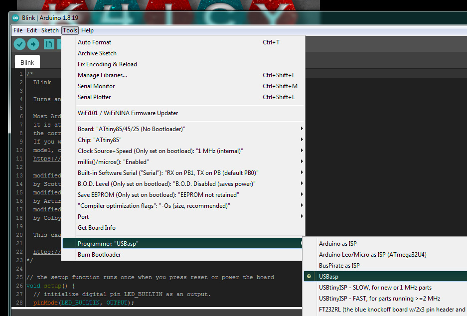 . Step 3: Burn the Bootloader. If you're programming a fresh ATTiny85 chip, you'll need to Burn a Bootloader even if plan on uploading a sketch without a bootloader as certain 'fuses', or memory bits, needs to be set on the initial setup of the chip. . ..... 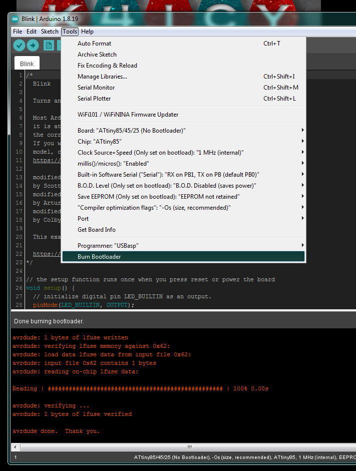 . Step 4: Upload Sketch to an ATTiny85 Using the USBasp Programmer. If uploading fails due to an error such as "device not available on COM...", either try again or try the USBasp programmer on a different USB port. . ..... 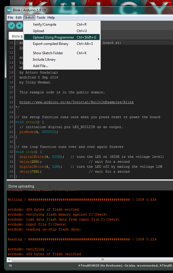 . . NOTE: If your ATTiny85 or AVR device has been setup by the Board Core to run at a CPU speed of less than 150 kHz, You may need to install a jumper on the "J3" or "JP3" header which will tell the programmer to upload at a slower speed. . ..... 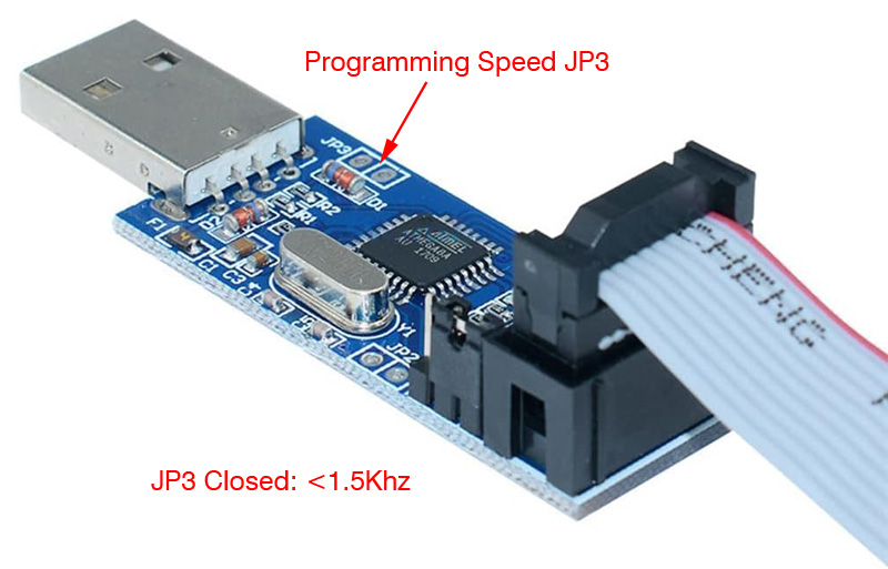 Your ATTiny85 should now be programmed! . . Brew Your Own: I'll be posting more here soon on how you can build your own USBasp for fun, or at least to augment its features. You can study this schematic - but please visit https://www.fischl.de/usbasp/ for more information along with firmware resources. . . .
Programming the ATTiny with an FTDI USB-to-Serial Interface . Uploading sketches using an FTDI USB-to-Serial interface can make working with the ATTiny85 a streamlined and efficient process. This method eliminates the need for a dedicated Arduino Uno or pricey Microchip programmer. Programming may even be possible with the ATTiny85 installed in its target circuit making it a convenient solution for ongoing development. The FTDI even allows for serial communication and debugging. I'll try to guide you here through the process, looking at the advantages, the setup process and potential pitfalls. The heart of this method is use of the Snapduino bootloader by Daniel Porrey which is a slightly limited feature version of the Optiboot bootloader with an added program called Tiny Tuner which is then removed after clock calibration leaving most of the 8k of programming space to play with. To find out more about this method before you dive in please check these out: https://www.hackster.io/porrey/snapduino-e5f0a5 Snapduino is a fun little educational project for young learners. https://github.com/porrey/Snapduino/releases/tag/v1.0.2 Here's the GitHub site, but you'll have to load the Boards Manager URL .jason. And watch the definitive how-to guide "Program ATtiny85 directly via USB" by Mr.T's Design Graveyard: .. .... . Programming ATTiny85's with an FTDI using the Snapduino bootloader offers several benefits as you can guess: Efficiency - Once the bootloader is installed and the ATTiny's internal clock is calibrated, further programming can be done directly via the FTDI interface, saving time and effort. Resource Management - Frees up your Arduino Uno or Nano for other projects after the initial bootloader burn setup, and your wallet will also feel free as well without the need for a dedicated programmer and having to buy more Arduinos. FTDI's are dirt cheap. Convenience - You should be able to plug in FTDI interface within whatever project your ATTiny85 has been employed (provided certain wiring or jumper provisions,) and sketch updating and uploading becomes pretty much straightforward. . Setup Prerequisites: On the hardware side you will need: • Your ATTiny85 microcontroller - can be a blank new chip. • Arduino Uno - initially set up as an ISP programmer. [SEE ABOVE SETUP GUIDE] • FTDI USB-to-Serial interface - You can buy them here: [Amazon Link 1] [Amazon Link 2] or search Amazon, eBay, AliExpress, Digi-Key and others. You can get them from $2-$12 depending on from where and if they use the generic FT232RL chip then an additional PC driver may be required. • A solderless breadboard, DuPont jumper wires • A 100nf capacitor (ceramic type, for reset line,) a 10k ohm resistor (for the reset line) and a 330 ohm resistor On the software side you will need the Arduino IDE of course and access to the Boards Manager Snapduino core - see link below. Step-by-Step Guide: Step 1 - Prepare the Arduino Uno ISP Programmer • Prepare the Arduino Uno as ISP Programmer • Connect the Arduino Uno to your computer. • Open the Arduino IDE and load the "ArduinoISP" sketch from File -> Examples -> 11.ArduinoISP -> ArduinoISP • Upload the "ArduinoISP" sketch to your Arduino Uno. • Now install the 10uF capacitor (as described above.) Step 2 - Install the Snapduino Bootloader • Open Arduino IDE and go to File -> Preferences • In the "Additional Boards Manager URLs" field, add the following URL: https://raw.githubusercontent.com/porrey/snapduino/IDE/package_porrey_snapduino_index.json • Go to Tools -> Board -> Boards Manager..., search for "Snapduino," (by Daniel M. Porrey version 1.0.2) and install it. Step 3 - Burn the Bootloader onto the ATTiny85 • Wire the ATTiny85 to the Arduino Uno according to the ISP Programming instructions above. • Select the Snapduino bootloader under Tools -> Board -> Snap Circuits -> Snapduino. • Tell Arduino IDE to use the Arduino Uno as the programmer: Tools -> Programmer -> Arduino as ISP. • Select Tools -> Burn Bootloader to burn the Snapduino bootloader onto the ATTiny85. Step 4 - Setup the FTDI USB-to-Serial Interface with the ATTiny85 • On a solderless breadboard, place the ATTiny85 and connect the FTDI USB-to-Serial interface to the ATTiny85 following the schematic below... The schematic has been updated from the one shown in Mr. T's video as the ATTiny85's Reset pin requires a 10k ohm pull-up directly at the pin. The capacitor's purpose is to allow only a short ground-going logic low pulse which is compared against the logic hi from the resistor. Make sure that RX, TX, VCC, GND and DTR are connected correctly as various brands may assign their pins differently than the schematic shows. The LED and associated 330 ohm resistor (on pin 7, digital pin 2) is set up for convenience when using the Blink sketch to test. • Connect the FTDI interface to the computer's USB port. An additional driver may be required for the computer to recognize the interface which is out of the scope of this article. Please search YouTube for FTDI troubleshooting. • As removing the Arduino Uno from the computer may have reset things in the IDE, you may need to re-select the board: If so, select the Snapduino bootloader under Tools -> Board -> Snap Circuits -> Snapduino. (click image to enlarge) .... 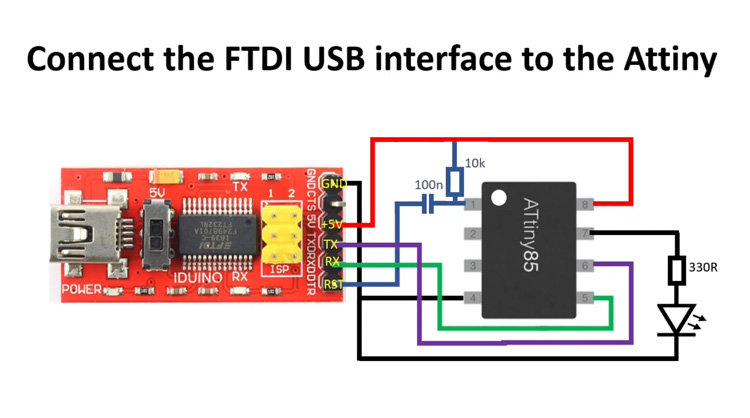 Step 5 - Calibrate the Internal Oscillator with built-in TinyTuner • After wiring up the ATTiny85 to the FTDI, open the Serial Monitor in the Arduino IDE. • Set the baud rate to 6900. • Plug in the USB cable from the FTDI to the computer's USB port. A dialog from the TinyTuner program should load up on the Serial Monitor. If not, check the baud rate, check your computer's Hardware Configuration for the presence of the FTDI device, and possibly try restarting Arduino IDE. • At the Serial Monitor prompt, enter the lowercase letter "x" as stated in the dialog text. Do this repeatedly until the dialog tells you that calibration has ended successfully. You may have to enter "x" at least a dozen times. This procedur is only required once and TinyTuner will then be removed. • Once completed, TinyTuner will calibrate the ATTiny's internal 8 MHz oscillator by storing a calibration factor into the OSCCAL register at the time of bootloader startup. Normally, the fabrication factory (Microchip) will preset the oscillator within 5% to 10% of the intended 8 MHz, which is too much out of tolerance for Serial communications. This is one reason why a UART/USART was not included in this package. If your ATTiny85 is this much off the mark you won't be able to program it with an FTDI. TinyTuner's adjustment at the OSCCAL register with get this within 1% to 5%. TinyTuner will then delete its programming and the bootloader will be reduced to under 400k which will leave you with ~7616 bytes to program with. . ... 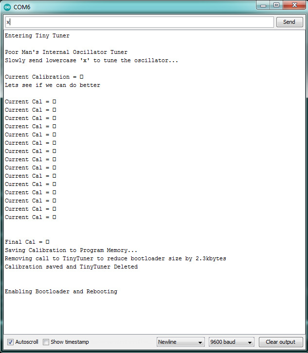 . (My example above shows a calibration with TinyTuner, the boxes are supposed to be tolerance indication letters, but there's something off in my setup.) Step 6 - Programming • Ready you sketch with any consideration afforded the ATTiny85 using the Optiboot bootloader. • Ensure that the Snapduino bootloader under Tools -> Board -> Snap Circuits -> Snapduino is setup as the active Board as this core is required when compiling and uploading sketches to any ATTiny85 using the Snapduino bootloader! • Ensure `AVR ISP` is selected under Tools -> Programmer. • Program your ATTiny85 using Upload (Sketch -> Upload) as you have with the Arduino Uno. You can now upload sketches directly to the ATTiny85 using the FTDI interface! . Potential Pitfalls and Issues: 1. Calibration Sensitivity - The internal oscillator of the ATTiny85 can (and often always will) be inaccurate. Since the oscillator is comprised of a resistor/capacitor topology, it will be sensitive to IC body temperature and even vibration. Proper calibration using the included TinyTuner is crucial for reliable serial communication and programming! 2. Board Manager Core Selection - This setup only uses the Snapduino core and must also be selected in the Arduino IDE when uploading sketches. Attempting to use a different Board setting will result in failed uploads. With any cause for reliance on a 'cloud' feature, there's no guarantee that the Snapduino core will be around for ever, much less ever able to download. 3. The ATTiny using this setup can only run at 8 MHz internal, 16 Mhz if using pins 2 and 3 to host a crystal. 4. Baud Rate Matching - Ensure that the baud rate in the Serial Monitor is set to 6900 for the Tiny Tuner calibration process and any subsequent uploads. 5. Connection Stability - Double-check all connections between the FTDI interface and the ATTiny85. Loose connections can cause upload failures or communication issues. 6. Serial.print is not available with this core as it is with the aforementioned ATTinyCore (above) so you must use SoftwareSerial with the required library. With SoftwareSerial, you will then be able to send serial data directly through the FTDI interface, though SoftwareSerial will consume 2k of program memory! . ... 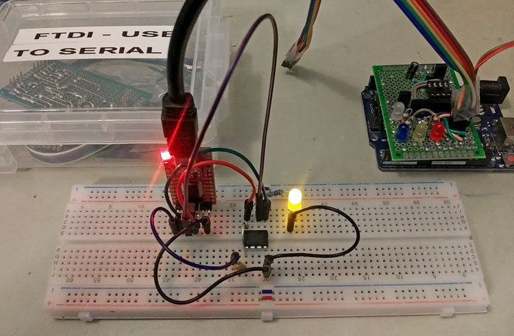 . And finally, it is true that the DigiSpark direct-to-USB ATTiny85 method is a bit more convenient than this method, not requiring an FTDI interface, but first, its bootloader consumes 2k of the 8k given, which makes it a very limited device, and second, the FTDI method allows you to remove the ATTiny85 chip from the FTDI. Wiring to an FTDI can be made on any project, perhaps using a few removable jumpers to allow for programming on the fly. I present this as an exercise in using this tiny and humble marvel. . .
Make a USB Direct-Programmable ATTiny85 (The Digispark) Make your own Digispark clone - Use like an Arduino or as an HID interface, and no programmer required for uploading sketches! .
This section will show
you how to make a Digispark which is a small ATTiny85 development board
that can be directly connected to a USB . . .
• ATTiny85
Microcontroller: The heart of the Digispark,
featuring ~6.5kB of flash memory (of the ATTiny85's original 8 kB,
considering bootloader), .
How
Does the Digispark Function?
• The Digispark is programmed using the Arduino
IDE, which makes it accessible even for beginners.
• The Digispark can be powered directly from the
USB port or through an external power source connected to its power
pins.
• The
Digispark’s 6 I/O pins are versatile and can be used for various
functions such as reading sensor data, controlling LEDs, or interfacing
with other devices.
• Due
to its small size and the limited number of I/O pins, the Digispark is
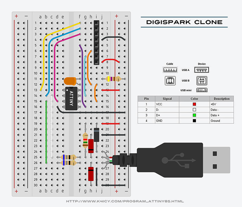
best suited for simpler projects or as a part of a larger system. . A Bit on the Micronucleus BootloaderThe Micronucleus bootloader [not to be confused with mononucleosis] is a lightweight USB communications specific bootloader designed specifically for the ATTiny85 and similar microcontrollers. Here's a quick breakdown of how it communicates with the PC's USB interface: Micronucleus Bootloader and USB Communication USB Low-Speed Emulation: • The ATTiny85 does not have native USB hardware, so the Micronucleus bootloader emulates a USB low-speed device entirely in software. This is done by bit-banging the USB protocol using the microcontroller's I/O pins. The D+ and D- lines of the USB port are directly connected to two of the ATTiny85's pins and additional components including two 3.6V Zener diodes and a 1.5k ohm pull-up resistor on the D- line ensure proper electrical operational conditions through the USB port. Timing Accuracy and OSCAL Register: • USB communication requires precise timing to function correctly, which is a challenge because the ATTiny85 relies on an internal oscillator that can have significant deviation (typically ±10%). To achieve the necessary timing accuracy, the Micronucleus bootloader utilizes the ATTiny85's OSCAL (Oscillator Calibration) register. • The OSCAL register allows for fine-tuning of the internal oscillator's actual frequency - no wait states or timer/ISR tricks involved. During the bootloader's initialization, with poling between the USB driver and the bootloader, the bootloader can adjust the oscillator's frequency by setting the OSCAL register to a value that brings the timing within the range required for USB communication. • The calibration process ensures that the ATTiny85 can meet the timing constraints of the USB protocol, but this only applies during the brief period when the bootloader is active as well a during instances when library-based protocols are used to send HID instructions or serial communications, such as when acting as a keyboard, mouse or joystick or sending serial data. Communication Process: • When the Digispark is plugged into a USB port, the Micronucleus bootloader takes control and begins communicating with the PC. • The PC recognizes the device as a USB low-speed device and initiates the standard USB enumeration process. • The bootloader listens for commands from the PC, typically to upload new firmware and once the communication is complete or after a timeout, the bootloader hands over control to the uploaded firmware or the existing ATTiny85's application code. USB Driver on the PC: • A custom USB driver is required on the PC to recognize and communicate with the Micronucleus bootloader. This driver translates the USB protocol into a format that can be handled by the bootloader and vice versa. . STEP 1: Let's Make A Homebrew Digispark! Digispark boards can be found at many sites for really cheap - why make your own? Building your own Digispark clone offers more than just a DIY challenge, it can be an educational experience that deepens your understanding of microcontrollers and electronics, especially that of an alternative to the Arduino Uno. By crafting your own Digispark yourself, even with a bare 8-DIP ATTiny85 IC, you can gain insight into how each component interacts, even with your PC's USB port, making it easier to troubleshoot and modify your projects. This Digispark clone project allows for customization, whether you need a specific pin layout, want to add unique features, or simply aim to integrate the board seamlessly into a larger projects. Moreover, building your own can be rewarding and cost-effective, especially when you need multiple units or wish to experiment with different configurations - yours doesn't even need to leave the solderless breadboard. The Digispark's ease of programming and tiny size will inspire you to invent more projects, increasing your technical skills and providing a more personalized tool tailored to your specific needs. You may find setting up your Digispark to be a little daunting, and you may certainly run into a snag or two. Hopefully, I've given enough here to get most of you up and running. Luckily, the Digispark and ATTiny85 has a pretty large following, with many online resources and YouTube videos to help. From here on, we'll establish the circuit, prep the ATTiny85 and your PC, then install the necessary resources, and finally, we'll get this ATTiny platform up and running. . Here's the schematic: . There are a few key components required for USB enumeration and operation, namely, a USB connection, the protection diodes (3), a pull-up resistor on the D- line, two current-limiter resistors on the D- and D+ line and an ATTiny85 microcontroller IC. The rest of the components are optional. The ATTiny85 [U2] can be either a surface mount package or an 8-pin DIP. If using the through-hole 8-pin DIP package, it's suggested to use an IC socket for convenience. Other ATTiny models can be used provided the Micronucleus bootloader is compatible and there's enough SRAM space leftover for adequate operation of any desired sketch. The ATTiny85 must be programmed initially with the Micronucleus bootloader prior to installation in the circuit, and that can be done with an Arduino-as-ISP programmer, a USBasp programmer or any other device capable of burning bootloaders to AVR MCU's. Header's [J5 and J6] can be male header pins, female DuPont cable pins or solder points to gain easy access to the I/O pins of the ATTiny85 after programming with the Digispark. The USB interface can connect to your computer with whatever you have on hand. The Digistump Digispark version has a set of USB / A contacts built into the the PCB. If you choose to do so through JLCPCB or PCBway, make sure you specify a PCB substrate thickness of approximately 1.6 mm (0.063 inches). This thickness matches the standard dimensions for a USB Type-A male connector, ensuring a snug and secure fit into a USB port. Additionally, the edges of the PCB must be carefully designed and plated with gold or another conductive material to create the necessary contacts as the standard tinning will wear out quick. The width of the PCB should be around 12 mm (0.472 inches) to fit properly within the USB port. The easiest way to connect is to sacrifice a USB cable. Make sure it has the four required conductors to carry data as well as power. Cut, strip and tin each lead to wire them to your proto-board, or pair them with a 4-pin header set or DuPont jumper pins for easy connection to a solderless breadboard. Another convenient method for USB connection, as shown in my example, is to purchase a set of USB-Mini female socket breakout boards which can be soldered to header pins and allows for the convenient use of a standard USB-Mini phone charger cable and wall brick to power your Digispark clone when apart of your PC's USB port. Two 3.6 Volt-rated Zener diodes [D2 and D3] must be connected each to data lines D- and D+ and offers overvoltage and voltage spike protection for your PC's USB port. [R2 and R3], each 68 ohm resistors serve to resist current surges. Other protection measures can be used including a dedicated USB interface buffer IC, but it is suggested to always plug any home made USB device through a USB hub just in case something like an unexpected short is present. [R1] is a 1.5k ohm pull-up resistor, signifying an enumeration ready-state for the USB port, but is primarily intended for open-collector logic connections. [J2 and J3] are optional jumpers. They must be closed to allow for uploading to the ATTiny85, but will allow you to use the ATTiny's pins 2 and 3 for you project, avoiding contention from the pull-up resistor or Zener diodes. [D1] is a Schottky diode which serves to protect power backflow into the USB port. A Schottky diode should be used over a standard rectifier diode as the voltage drop is far less than the latter. Optionally, you may install the voltage regulator circuit which will provide a steady 5 volts when powered from an external 6V to 12V source. [J1] can be a convenient header terminal for that source or a 3V to 5V source such as from a coin cell or power supplied by a larger project circuit for which the Digispark clone will be integrated with. The 5V regulator consists of a small LM78L05 which is the same package as a standard TO-92 package transistor, two filter capacitors and a power indicator LED with its current limiting resistor. These through-hole versions are getting harder to find, but there are countless LDO surface mount versions with much better characteristics. Keep in mind that this part has a 100 mA max rating. The regulator circuit can be omitted if you're planning on running just off of the USB port or within another project. [LED2 and R5] serves as the standard Digispark Blink Test LED on Arduino (ATTiny) pin 1 (PB1, IC pin #5) that can be turned on or off within your sketch using the pin descriptor "LED_BUILTIN". This can be disconnected from your ATTiny85 by removing a jumper from [J4]. [J5 and J6], as mentioned earlier, can be any method of allowing access to each pin of the ATTiny85, including the VCC and GND lines. . Here's the list of parts with ordering links: D1 - 1N5817 Schottky Diode, 20V, 1A [DigiKey Link] D2, D3 - BZX55C Zener Diode, 3.6V, 500mW [DigiKey Link] U1 - L78L05CZ (LM7805 eq.) Linear Regulator, TO-92, 5V 100mA [DigiKey Link] U2 - ATTiny85 (Microchip Technologies) 8-Pin AVR, 8K Flash [DigiKey Link] IC Socket, 8-Pin [DigiKey Link] USB-Mini Female Socket Breakout PCB Modules [Amazon Link] USB/A Male Plug Breakout PCB Modules [Amazon Link] 2.54mm Single Row PCB Female DuPont-Type Header Socket Connector Strips [Amazon Link] All other passive components including resistors, capacitors, LED's and header pins can be found from Amazon, eBay, AliExpress and others in bulk package kits for nominal prices, whereas searching for single-piece items on DigiKey will prove to be more expensive. Resistor Assortment, 1/4W (Including 68 ohm) [Amazon Link] LED Assortment, 5mm, 5-color [Amazon Link] Ceramic Capacitor Assortment (100nF and less) [Amazon Link] Electrolytic Capacitor Assortment (0.1uF and more) [Amazon Link] . Let's setup a solderless breadboard prototype: Setting up a circuit on a solderless breadboard is a great way to work out the kinks, testing the components, PC drivers and Arduino IDE cores. . . The setup above follows the provided schematic minus the voltage regular circuit. The red parts connected to the USB data lines are the Zener diodes and the black one is the Schottky diode. The stripe represents the cathode (line part of the schematic symbol). There seems to be a little confusion with a few schematics found online with the Schottky diode, whose job it is to keep any voltage presented on the circuit from flowing back into the PC's USB port. Some have it backwards, but the arrow of the symbol represents the preferred 'voltage' flow (to ground). The Zener diodes appears to be reversed in the circuit schematic because it's designed to conduct in reverse bias when the voltage exceeds its breakdown voltage, allowing it to regulate (or clamp voltage) in applications like voltage regulation and overvoltage protection. The cathodes are connected to the Data lines. Please note the 8-pin DuPont header socket at the top. Yes, in this example it's redundant to put one of those on a plug-in prototype breadboard, but it will give you a sense of functionality when you solder it to a permanent protoboard. One you've uploaded a great sketch, you can re-wire this board to suit your project. In fact, most Digispark boards use a serface mount version of the ATTiny85, which makes for a very small add-on microcontroller when you need one in a larger circuit, but if you build a Digispark close that uses a socketed 8-pin DIP package, you can remove the ATTiny85 and use that in your circuits. Take a look at my build below... . .
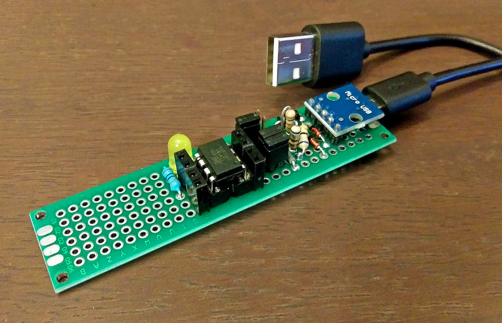
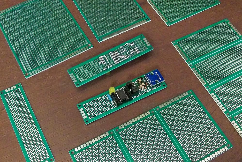
.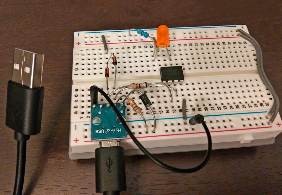 I used a Micro USB breakout board to allow for tinkering on a nearby table while accessing the PC's USB port. Once a sketch is uploaded and additional sensors or a display is added, the same USB board can be used to get power from a phone charger. . Moving to a Soldered Prototype Board: [I'll add an example soldering map here soon] Taking your circuit to the next step which lies between a solderless socket board and a professionally manufactured PCB can be an adventure. Soldering real part together in a form compact enough to be used practically is as much of an art as it is a skill exercise. Some folks just place their parts down wherever, connecting each lead with insulated jumper wires while others consider dimensions, lead proximity as well as aesthetics, either way, whether you use the blessing of real estate granted with large prototype boards or nest everything together like a clock maker into the smallest of boards, this is really up to the builder and as long as the product works as intended in the end, that's all that matters. As far as my Digispark prototype, I used a USB-Micro breakout board which wast mated to my protoboard via header pins. I mounted it upside down which sandwiched the actual connector between the boards giving it resiliency. I also placed separate DuPont female sockets adjacent to the pins of the ATTiny85, which is also socketed. This gives the user a logical bearing on which pins are where. The USB Data line are jumpered before the ATTiny85 as to allow for circuit separation when those pins are needed in non-USB operation, and a jumper was added to take the 'blinky' LED out of circuit so that Pin 1 could be used for other tasks. By happenstance, there was a bit of unused space left over on the protoboard and I decided to not remove it as this would be convenient for adding any interesting circuits or at the least, I could add a voltage regulator. A few construction tips to note: 1) Save the leads clipped from components as they can be used to bridge longer distance between solder pads. 2) Skillful solder 'blobbing' can be used to jumps between adjacent holes. 3) Carefully just the parts themselves as 'jumpers' to cross paths rather than adding unsightly jumper wires. 3) Consider buying single-sided solder padded prototype breadboards if possible as the double-sided kind tends to yield more accidental shorts. 4) And finally, plan out your parts and soldering layout solution on graph paper first, pre-placing your parts first to gauge their best fit. And consider where you may also have trouble soldering once other parts are in place. . .
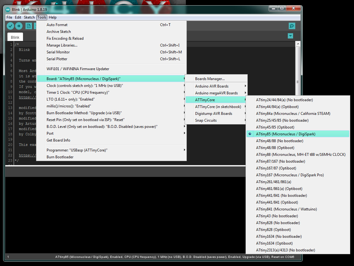
. A custom manufactured PCB: [I'll add my own take here soon, along with Gerber files for sending to your favorite PCB manufacturer] . STEP 2: Burn The Micronucleus Bootloader to an ATTiny85 . Mount the ATTiny85 in the programmer: Before mounting the ATTiny85 into the Digispark circuit, you'll need to set it up in your choice of AVR programmer such as a USBasp or Arduino as ISP to burn in the special Micronucleus bootloader required to get the ATTiny85 interfacing your IDE directly through USB. Please follow the steps according to the instructions in the above section on setting up the programming interface using your Arduino. . Setup chip parameters and burn the Micronucleus Bootloader: To get the most control of your Digispark ATTiny85, it is suggested to use the Spece Konde ATTinyCore board core [Instructions Above]. The Spence Konde ATTinyCore can be installed automatically to update the Arduino IDE Boards Manager by adding: http://drazzy.com/package_drazzy.com_index.json inside the Additional Boards Manager URL list. Then go to the Boards Manager inside of the Tools menu. If the URL doesn't work, you'll have to install ATTinyCore [as per the instructions above], however, I have found that loading the Micronucleus bootloader may fail in the manual core setup due to some naming convention error (I haven't figured this out yet.) Once added, go to Tools and choose "ATTiny85 Micronucleus / Digispark" under Tool => Boards => ATTinyCore => . .
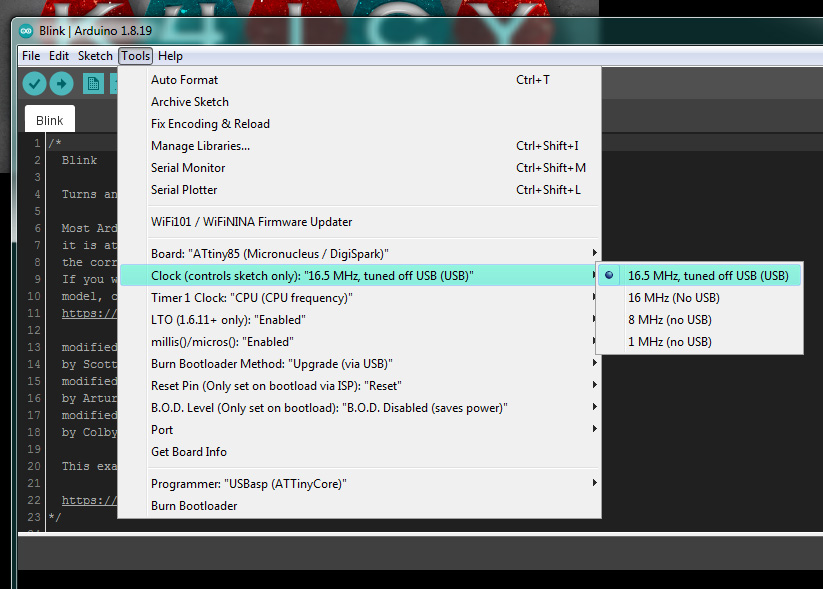
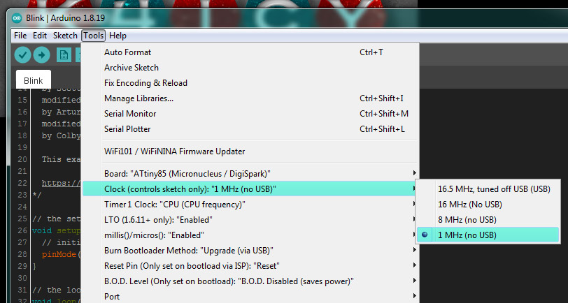
. Now, we'll go through some of the chip-specific settings: This setting deals with the CPU Clock set for the running uploaded sketch. When burning the bootloader for the first time to a fresh ATTiny85, Choose "16.5 MHz, tuned off USB (USB)". The Micronucleus bootloader will tune the OSCAL register to match the 16.5 MHz communication speed of the USB port and will then save that registry value for future internal oscillator calibration when uploading and running other sketches. . .
. Leave the Timer 1 Clock set to "CPU (CPU frequency)". . .
. Leave the LTO "Enabled". . .
. Choose to be "Enabled" if you'd like to use the millis() and micros() calls in your sketch. If you plan to use an AVR library that includes and alternate then disable this option. Also disable if you don't plan on calling the time within your sketch as you can save some program flash memory. . .
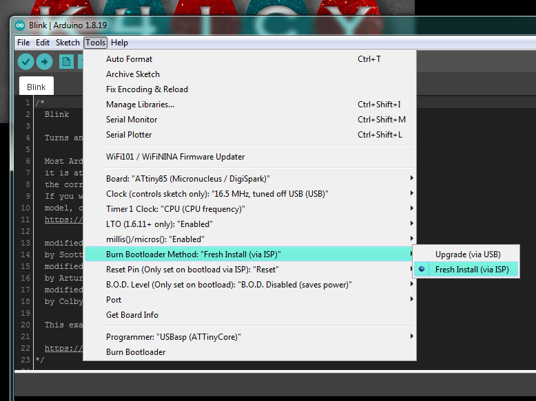
. Under "Burn Bootloader Method:" you have two options. When you are FIRST loading the Micronucleus bootloader to a fresh ATTiny85 chip, you must choose "Fresh Install (via ISP)" which is the base bootloader package. AFTER you have installed your Digispark including the ATTiny85, you can then freshen up your Micronucleus bootloader through the Digispark's USB port without removing the chip or using a programmer by choosing the "Upgrade (via USB)" option as the original bootloader will negotiate the clock calibration and auto-programming protocol. . .
. The Reset option for the ATTiny85's Pin 1 can be set here, but only on burning the bootloader via ISP. When left as the default "Reset", pin 1 will work as the typical Reset option (connect temporarily to GND) along with being a "soft I/O" pin, able to detect HIGH on digital read, as well as with a truncated analog read capability. However, you can choose to (semi-)permanently designate pin 1 as a regular I/O pin, giving you 6 total I/O pins, and resetting can only occur during the sketch uploading procedure via USB by means of the bootloader. WARNING: Once the "GPIO" option (no reset on pin 1) is set when burning the bootloader via ISP, the ONLY way to change pin 1's functionality back to being a Reset pin is to do so with a High Voltage Resetter - Schematic and Sketch for this device are in the "Fuse Setter" section below. . .
. B.O.D., or "Brown Out Detection" will reset or shut off your ATTiny85 in the even the supply voltage (VCC) goes below a certain threshold. Undervoltage can cause Flash or EEPROM corruption, or worse, any important data communication or pin control to any crucial device to be corrupt and fail, which is why B.O.D. can be a valuable protection feature. However, the B.O.D. consumes some current and disabling it will be best for circuits intended to be powered with a small battery source. . .
. Choose your intended ISP programmer for uploading the bootloader, i.e.: your Arduino as ISP or your USBasp. This setting will no longer apply once you install your USB Digispark. . .
.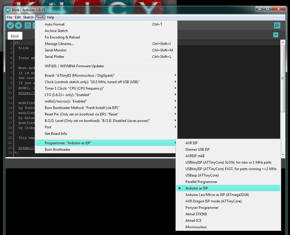 With all option parameters set, burn the Micronucleus bootloader to the ATTiny85 via you ISP programmer... . .
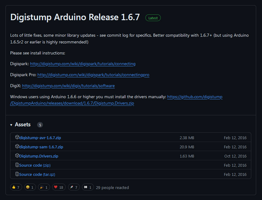
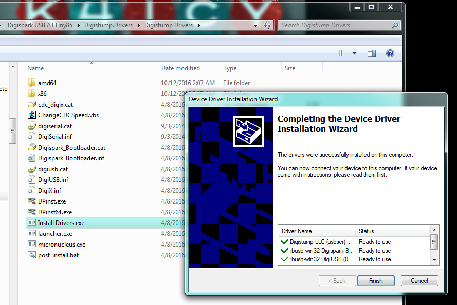
.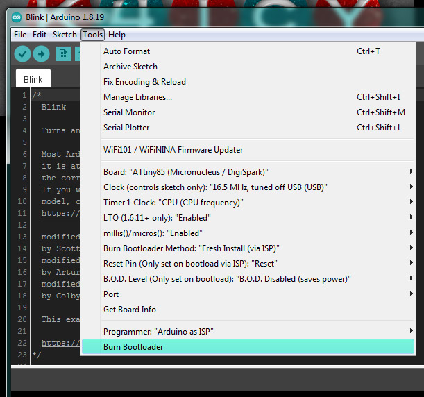 If you get the 'success' indication in the Arduino IDE status window, you can now install your ATTiny85 chip into its socket or solder it into place. If you get an unfortunate error trying to burn the bootloader, you'll have to do some troubleshooting beyond the scope of this tutorial. I had this issue when trying to use the ATTinyCore board core I had set up manually in my "Hardware" folder. I'm not sure why it failed but it mentioned something about an "error in naming." This is an alternate source or two which you can try, including a plain-Jane board core for the Digispark without any settings options. . STEP 3: Download Digispark USB driver and libraries: Visit: https://github.com/digistump/DigistumpArduino/releases . . Download: "Digistump.Drivers.zip" . . STEP 4: Install Digispark USB driver: . . Unpack and run "Install Drivers.exe". If successfully installed - Plug in your ready Digispark or Digispark clone into a USB socket and allow Windows to install the drivers for the detected device. Inside your Device Manager in Windows' Control Panel, you should see no driver issues. . .
. STEP 5: Upload a sketch: Open the standard Blink sketch under Examples in the Arduino IDE. The "LED_BUILTIN" pin designator should be associated with you Digispark ATTiny85's pin 1. Go to your Tools menu and check that the Board is set to "ATTiny85 (Micronucleus / Digispark). Under Clock, you should set the clock to 1 MHz, 8 MHz if you intend on removing the Digispark from the USB port of independent operation. 8 MHz will provide more performance for peripherals and operations but will consume more power. 1 MHz will provide the most battery life. Each of these "(no USB)" settings, once implemented on the Digispark's ATTiny85 will run at calibrated speeds. You can leave the speed set to 16.5 MHz if you intend to keep your Digispark dev board continually attached to the USB port. The 16 MHz option may be available if the internal CPU is running off of PLL mode. [I'm not sure - but it's worth a try.] . .
. Now Upload the sketch... . .
.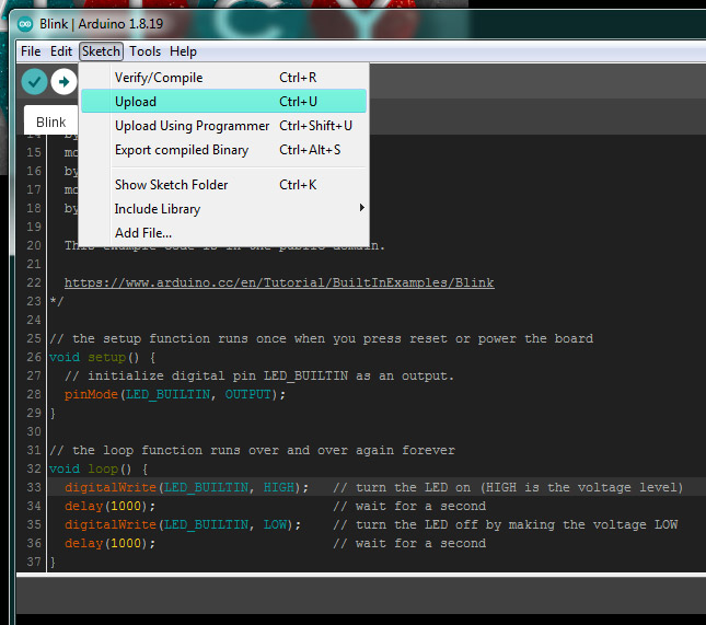 You'll be prompted to "plug in the device" within 60 seconds... . .
.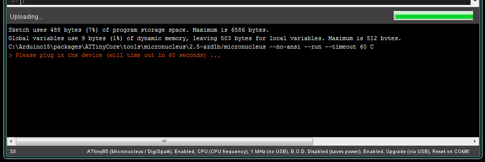 If you don't plug in your Digispark within a minute it will time out and abort. If your Digispark is already plugged in - you must remove the Digispark and plug it in again as the Micronucleus bootloader will re-initialize so that it can re-calibrate the CPU clock a await for new instructions to be transmitted via USB. If you are providing constant external power to the Digispark, you must disconnect the power so that the bootloader can re-initialize via fresh connection to the USB port. . .
. Your sketch should now be loaded into your new clone Digispark and the LED on pin 1 should be blinking. If so, congratulations! You're now ready to tinker with a Digispark ATTiny85. . Include libraries and example sketches: There are many libraries and associated example sketches available for the Digispark, however, without the original Digistump website available, the process of of installing them is a bit tricky. FIRST, re-visit: https://github.com/digistump/DigistumpArduino/releases and download "digistump-avr-1.6.7.zip". Next, unpack the Zip file and inspect the folders contained... You'll find a folder named "libraries". . .
.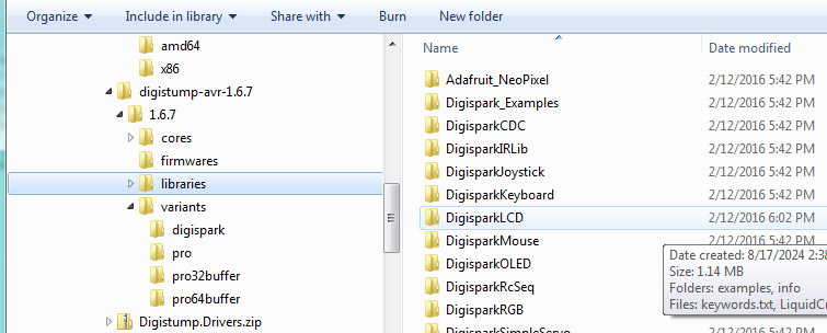 COPY the included folders then locate your Arduino libraries folder: C:\Program Files (x86)\Arduino\libraries... or wherever your library folder is located. PASTE these new folders into Arduino's library folder. Launche the Arduino IDE and see if you have these new sketches inside of Examples. . .
.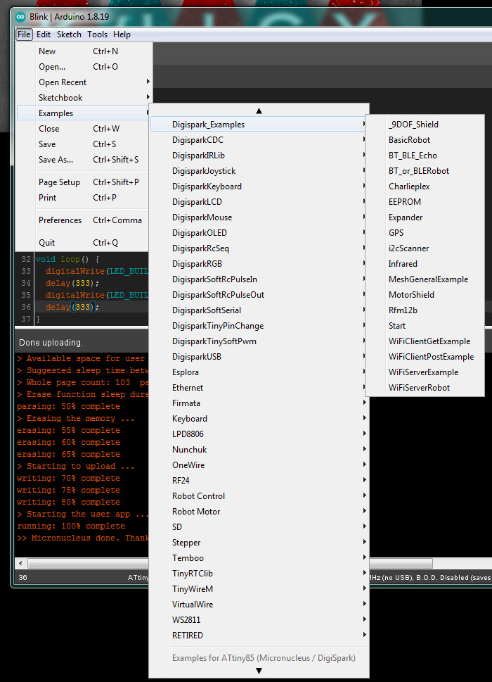 Issues and workarounds: Since these examples and libraries are not automatically loaded, and since information on these are harder to get at, you'll certainly run into some issues. You may run into library conflicts: for instance, "keyboard.h" may exist in other examples loaded from other sources. The solution is to install a separate instance of Arduino IDE, one setup JUST FOR your Digispark, where only these examples and libraries are populated. Fixes for every problem are outside the scope of this tutorial, so you should, of course, go hunting for other examples as well as helpful YouTube videos on all-things Digispark. An additional source for Digistump/Digispark resource files can be found here: http://sourceforge.net/projects/digistump/files/ This version (1.5) is a bit older than the Github source, but contains some interesting resources, and I believe versions for other OS's including Mac and Linux.. The following video by Mr. T's Design Graveyard offers a complete tutorial on building your own Digispark: .Make your own Digispark USB! [Mr. T's Design Graveyard]
.. Good luck! . .
Get the ATTiny Talking to the Serial Monitor - Using Only 1
Pin . APPLICATION WARNING: As the internal oscillator of the ATTtiny85 can be off-frequency (typically ±10%), the user may have trouble implementing this technique due to the speed precision requirement of the USB communications / Serial protocol. Certain solutions such as using the Digistump/Digispark or Snapduino bootloader, implementing a call to the OSCAL register with an experimentally determined value or using a dedicated 16 MHz crystal (on pins 2 and 3) may be required. If you're familiar with programming ATTiny's from the Arduino IDE, you know that these tiny chips offer decent flexibility but come with some limitations, particularly in serial communication. The ATTiny85, for instance, only has a Universal Serial Interface (USI) instead of a Universal Asynchronous Receiver/Transmitter (UART) that bigger chip such as the ATmega328p, making standard serial communication challenging. However, using an FTDI USB-to-Serial interface and the SoftwareSerial option, more particularly, the Send-Only SoftwareSerial library by Nick Gammon, you can establish serial communication with just ONE PIN! Why use one pin, you may ask? Isn't serial communications a two-pin requirement? Using a single pin for serial communication is beneficial when working with pin-limited microcontrollers like the ATTiny series. So obviously, using only a single pin allows you to reserve the other few pins for different functionalities, which is crucial to the viability of the mroe small projects chips like the ATtiny85 are suited for. ....  Setting Up the ATTiny for 1-Pin Serial Communication: Reference the simple schematic. We'll use the ATTiny85 as an example... Here, we'll assume that you have the Arduino IDE running along with your chosen core and have the bootloader installed and etc.. FIRST: Download and install Nick Gammon's Send-Only Software Serial library from his GitHub link: https://github.com/nickgammon/SendOnlySoftwareSerial You'll need to remove the part of the download file's name "-master". Then you'll need to go into your Libraries Manager inside of Arduino IDE and use the Install from ZIP option to install it. You'll need to wire up your ATTiny microcontroller IC to an FTDI USB-to-Serial interface as follows: • Connect the FTDI's RX pin to eh designated Serial Output pin (TX) on your ATTiny. (Remember: RX to TX, TX to RX) • Connect the FTDI's GND to the ATTiny's GND. • You can power the ATTiny from the VCC of the FTDI - ONLY if there's no more than an LED or two running from the ATTiny85 as not to tax the FTDI of USB port, otherwise, connect each device to appropriate sources according to good practice. The RX device should never be running at a lower voltage (ie. 3.3v) than the TX (ie. 5v) for obvious reasons. Is it safe to connect an ATTiny running on a 5v battery to share VCC with a 5v source USB device? I can't tell you for sure - this is beyond the scope of this article. Here is a code example: .
. Upload this code to your ATTiny via your programmer, and open the Serial Monitor in the Arduino IDE with the baud rate set to 9600 and the Com port set to that of your FTDI. You should see "Hello from ATTiny!" every second. . Advantages: These are obvious, for one, you get to free up a pin to use for another purpose. The SendOnlySoftwareSerial libary is pretty straight forward, and just as with Arduino IDE's SoftwareSerial library, you simply replace the call "Serial" with your own naming; "mySerial". You can even use more than one pin for additional serial outputs! For instance, devices like the DFRobot MP3 Mini can operate with controls sent over one pin from the mcu's TX pin to this device's RX pin allowing you to run more than one device at once. Disadvantages: No receiving capability, but this is also obvious. Speed Limitation: Software serial communication can be slower and less reliable than hardware UART! Large memory requirement: Any use of of the Serial protocol will use up a large portion of SRAM space, and may even be too large to use on the smaller ATTiny's! . This method should be compatible with several non-UDPI ATTiny type microcontroller IC's, including the ATTiny13, ATTiny24, ATTiny44, ATTiny84, ATTiny25, ATTiny45 and ATTiny85, and each of these chips should be able to utilize the Send-Only SoftwareSerial library, enabling serial communication with one pin. . Receiving Serial Data: To receive serial data from a PC, you can use the Receive-Only SoftwareSerial library, also by Nick Gammon, which you can get at this link: [LINK] However, this requires a different setup and another pin dedicated to RX if you wish to use this in conjunction with Send-Only. The fix here is to either use Arduino IDE's SoftwareSerial library which will give you both TX and RX pins or just try out Nick Gammon's complementary library. I'm not sure why I can't find the Receive version at his GitHub site, but the posted link goes to the appropriate Arduino.com article with a download of that library and sample files. For Receive via 1 pin to work, you would connect between the FTDI's TX and your ATTiny's RX. Alternatively, Spence Konde's attinycore for Arduino offers a built-in software serial solution that uses both RX and TX pins. While this is a robust alternative, again, it requires two pins, which may not be suitable for pin-limited projects. . So, using one pin to transmit serial data from an ATTiny microcontroller to a PC via an FTDI interface is a practical solution for debugging and simple serial communication. While this method has limitations, it does offer a way to achieve serial communication on a pin-limited microcontroller that doesn't normally come with the luxury of Serial. . . Enhancing ATTiny Coding for More Space and Speed Use Low-Level Commands and Bitwise Operations to Optimize Your ATTiny .
The ATTiny85 is often chosen for it's
small size
and low cost, and with these considerations it is thus a powerful yet
constrained microcontroller, perfect for the vast majority of simple
and small hobbyist tech projects. However, if the hobbyist
'maker' wishes to do more than blink a few LED's, its limited memory
and processing power necessitate more efficient coding techniques.
If you're already familiar with Arduino IDE programming, you
can
significantly improve your ATTiny85 projects by delving into low-level
commands, bitwise operations, and direct manipulation of internal
addresses. The following section will introduce these
concepts,
helping you optimize memory usage and increase execution speed, or at
least cause you to begin your search down the rabbit hole for more
information. .
Understanding Bitwise Operations . The following example uses classic high-level code to blink an LED connected to pin 0: .
.
This sketch, when compiled uses 466
bytes at (5%)
of program storage space out of a maximum of 8192 bytes on the
ATTiny85. .
. In the low-level code example, DDRB (Data Direction Register B) is used to set the pin's direction (an Input or an Output,) and PORTB controls the pin state. Bitwise operations set or clear specific bits, offering precise control over the microcontroller's I/O. "_delay_ms" can be replaced for the standard Arduino "delay" function if you wish and the included libraries at the top are not required for the address/bitwise operators.This sketch, when compiled uses only 292 bytes at (3%) of program storage space. A smaller size than the previous sketch which will certainly add up as the coding requirements increase. . Accessing Internal Registers Directly accessing and manipulating internal registers can save memory and speed up your code. The ATTiny85 has several registers for controlling its two timers, ADC (Analog-to-Digital Converter,) and more. . The following example sets up the ATTiny to blink an LED on pin 0 twice a second using delay() a high-level "Arduino" function: .
. This sketch, when compiled uses 466 bytes at (5%) of program storage space out of a maximum of 8192 bytes on the ATTiny85.
The
following example uses Low-Level Code to blink and LED on pin 0 twice a
second .
. In this low-level code example [above]:1. Setting PB0 as an Output: The DDRB register is modified to set PB0 (pin 0) as an output. 2. Configuring Timer1 in CTC Mode: The TCCR1 – Timer/Counter1 Control Register is set to enable CTC mode. 3. Setting the Compare Value: OCR1C is set to 244 to achieve a 250ms interval based on the the ATTiny's clock being set to 8 MHz using a Prescaler factor of 8192. 4. Enabling a Timer Interrupt: The TIMSK register is used to enable the Timer1 compare interrupt. 5. Setting the Prescaler: The TCCR1 – Timer/Counter1 Control Register sets the Prescaler to clk/8192. 6. Handling the Interrupt: The ISR(TIMER1_COMPA_vect) routine toggles pin port PB0, making the connected LED blink. . I know the low-level example above looks super complicated and takes up way more programming lines but this low-level approach is more efficient and precise, avoiding the overhead of the delay() function and enabling finer control over the timing. Believe it or not, this method essentially takes up less chip memory (308 bytes at 3% of program storage space) and even lets you blink the LED in the background while you can run other program functions, which is closer to a true "State Machine." Keep in mind that any other function requiring Timer1 will be affected, but the above example is just to show you the benefit of directly accessing the internal registers. I plan to add a more concise explanation and use examples of the ATTiny's Timer/address functions down the road. . Optimizing Memory Usage When memory is limited, every byte counts. Use the PROGMEM directive to store constant data in flash memory instead of SRAM. In this example, the message array is stored in flash memory, freeing up valuable SRAM. NOTE!:: The following example requires the added library: Send-Only SoftwareSerial by Nick Gammon, which you can get from GitHub [HERE]. Check out the above section for more info: Since the ATTiny85 (with only 8 pins) generally does not have a connected USB/bootloader interface or a dedicated UART, you'll have to use an FTDI interface. This is a common and inexpensive ($6) programmer (I'll add a description and links soon), and with the SendOnlySoftwareSerial library you'll only need to use one pin (as TX) which will connect to the FTDI programmer's RX pin. There's also a Receive-Only version. The included Arduino IDE Software-Serial will work too, but that takes two pins. For the following example, connect the VCC (pin 8) and GND (pin 4) of the ATTiny85 to the VCC and GND of the FTDI interface. "TX" as assigned (pin 0 of the ATTiny85) will connect to the RX of the FTDI interface. Use no other power source, and the FTDI can supply 3.3v or 5v, each will work. .
By leveraging low-level commands, bitwise operations, and direct register manipulation, you can greatly enhance the performance and efficiency of your ATTiny85 projects. These techniques are crucial for working within the paltry constraints of the ATTiny85, especially if you wish to do a lot, and it also allows you to maximize its more hidden capabilities. You're encouraged to experiment with these methods, learning more about them using the great resources of YouTube, Arduino's site and others, and yes, even your favorite chat-bot which can help you work out the code, and you may see significant improvements in your ATTiny's code's memory usage and execution speed helping you to a heck of a lot with an 8-pin MCU. I also strongly encourage you to check out Technoblogy.com (choose ATTiny85 from the right-side drop menu) for a lot of great low-level fun with lots of description and examples. There are still other register mysteries of the ATTiny85 which I hope to expound upon later including working with the ADC, using the timers to get PWM and Tone which is not featured through Arduino IDE on the ATTiny85, its universal communications setup (No native UART and limited Serial as with the 328p,) and other features using the fuse settings such as sleep modes, brown-out detect and others. With the right register control and libraries, we can even get I2C, SPI, Addressable LED control, 4-channel PWM and more! Did I miss or mess up anything in the above code? Fix it, test it and let me know - Thanks! . .
ATtiny Fuse Setter with 12 Volt Charge Pump
- A.K.A. "High Voltage Resetter" Will work for ATtiny13, ATtiny24, ATtiny44, ATtiny84, ATtiny25, ATtiny45 and ATtiny85 .. . Shown above: I
built this project as an Arduino Uno shield and it works as advertised.
Get control of your ATTiny's hidden settings,
change your
Reset pin to I/O Pin 6 (and vice versa) and un-brick your chip
Wayne's ATTiny
Fuse Reset with 12 Volt Charge Pump requires
only the 5 volt supply from your Arduino and generates .
Here's more information on reprogramming the
ATTiny's fuses by Ralph Bacon. .
Six, yes SIX, GPIO pins on an ATTiny85
[Ralph S. Bacon #87]
.
PCB for ATTiny85 Fuse Resetter (using JLCPCB
& EasyEDA)
[Ralph S. Bacon #144]
. . Get I2C, SPI, Addressable LED control, OneWire and more on your ATTiny Even without hardware communications features like UART, there are bit-banged solutions. This section is under construction, however, the following video by Ralph S. Bacon may answer your questions... .
ATTiny85 + I2C + SPI and more!
[Ralph S. Bacon #82]
.
Reducing Current Consumption with ATTiny Sleep Modes
Learn the Mystic Lullaby to Put Your
ATTiny to Sleep - Add Years to Your Battery's Life . Why Use Sleep Modes? Reducing power consumption is critical for battery-powered applications. Using the ATTiny's sleep modes, when applicable, can extend battery life significantly! The ATTiny85, like other microcontrollers in the ATTiny AVR series, provides several sleep modes to tailor power consumption to the needs of your application. . Sleep Modes Overview: The ATTiny85 supports multiple sleep modes, each offering different levels of power savings: • Idle Mode: The CPU is stopped, but internal peripherals like the ADC, Timer/Counter, and Watchdog Timer (WDT) continue to run. Use the following call in the enterSleepMode() function to use: set_sleep_mode(SLEEP_MODE_IDLE); // Set the sleep mode to Idle • ADC Noise Reduction Mode: Similar to Idle, but the ADC has a lower noise environment. This mode reduces noise during ADC conversions by stopping the CPU and I/O clocks while keeping the ADC running. Use the following call in the enterSleepMode() function to use: set_sleep_mode(SLEEP_MODE_ADC); // Set the sleep mode to ADC Noise Reduction • Power-Down Mode: The most power-saving mode; only the Watchdog Timer and external interrupts can wake the MCU. Use the following call in the enterSleepMode() function to use: set_sleep_mode(SLEEP_MODE_PWR_DOWN); // Choose the desired sleep mode • Power-Save Mode: Similar to Power-Down but with an asynchronous timer running. Use the following call in the enterSleepMode() function to use: set_sleep_mode(SLEEP_MODE_PWR_SAVE); // Set the sleep mode to Power-save • Standby Mode: The crystal (external) / resonator (internal) oscillator is kept running, but all other operations are halted, allowing a faster wake-up. Use the following call in the enterSleepMode() function to use: set_sleep_mode(SLEEP_MODE_STANDBY); // Set the sleep mode to Standby • Extended Standby Mode: Combines features of Standby and Power-Save modes, keeping the asynchronous timer running and the oscillator active. Use the following call in the enterSleepMode() function to use: set_sleep_mode(SLEEP_MODE_EXT_STANDBY); // Set the sleep mode to Extended Standby . Setting Up Sleep Modes: To use sleep modes effectively, you need to include the avr/sleep.h library in your code and configure the desired sleep mode using a series of functions, calls and macros. Here is the general setup. Inside the set_sleep_mode(.....) function call, the name of the mode will be inserted to tell the library which one to use. .
General Steps to Enter a Sleep Mode: 1. Include Required Libraries: You need avr/sleep.h for sleep functions and avr/interrupt.h for managing interrupts. 2. Set the Sleep Mode: Use the set_sleep_mode() function to specify the desired sleep mode. 3. Enable Sleep Mode: Use the sleep_enable() function to enable the sleep mode. 4. Disable BOD (Optional): Optionally disable the Brown-Out Detector for additional power savings using sleep_bod_disable(). 5. Enter Sleep Mode: Call sleep_cpu() to put the MCU into sleep mode. 6. Disable Sleep Mode After Wake-up: After the MCU wakes up, disable sleep mode using sleep_disable(). These steps can be adapted to any sleep mode by changing the argument to set_sleep_mode(). Each mode provides different levels of power saving and operational capabilities, so choose the one that best fits your application needs. . Waking the ATTiny: The ATTiny series, including the ATTiny85, supports various ways to wake from sleep modes. The primary methods include external pin change interrupts and other (internal) peripheral interrupts. Here’s an overview of these wake-up sources and how to use them: . • Using the Watchdog Timer for Wake-up The Watchdog Timer (WDT) can be used to periodically wake the MCU from sleep mode. Configure the WDT to generate interrupts at specified intervals. The maximum is 8 seconds, so for longer sleep periods using the WDT, use an incremental counter to cause an action after your desired time. .
. • External Pin Change Interrupts The ATTiny85 has external interrupts that can wake the MCU from sleep. These include the Pin Change Interrupt and an External Interrupt (INT0). 1. External Interrupt (INT0) The ATTiny85 has a dedicated external interrupt pin, INT0 (PB2 on ATTiny85). You can configure this pin to trigger an interrupt on a low level, any logical change, falling edge, or rising edge. .
. 2. Pin Change Interrupts The ATTiny85 supports pin change interrupts on all pins. This allows any I/O pin to wake the MCU from sleep when its state changes. .
. • Other Wake-up Sources Aside from external interrupts, the ATTiny85 can wake up from sleep using other peripheral interrupts. Some common ones include: • Timer/Counter Interrupts: Timer interrupts can be configured to wake the MCU from sleep modes. • ADC Conversion Complete Interrupt: In ADC Noise Reduction mode, the ADC interrupt can wake the MCU. • EEPROM Ready Interrupt: If the EEPROM is busy writing, the EEPROM ready interrupt can wake the MCU once the operation is complete. • Analog Comparator Interrupt: The analog comparator interrupt can wake the MCU when the comparator output changes. . ATTiny85 Current Consumption in Different Sleep Modes: With the ATTiny's sleep modes, you can design projects that are extremely power-efficient, making them ideal for long-term, battery-powered applications! Current consumption can be tricky to nail down and depend on the project and all connected devices and circuit components. Here are some general values for the current draw of the ATTiny85 operating in each particular sleep mode. The exact numbers on current consumption can vary slightly based on the specific conditions and operating voltage but the values provided below are typical and come from the ATTiny85's datasheet. Of course, for an accurate account on the current draw of any particular project and the estimation on battery life you'll have to take an ammeter to your project and use an online battery-life calculator for best results. The following numbers are based on the ATTiny85 running a 1 MHz CPU clock and at 3V. • Active Mode: Current Consumption: ~5-6 mA at 1 MHz, 3V • Idle Mode: Current Consumption: ~1-2 mA at 1 MHz, 3V The CPU is stopped, but the peripherals like ADC, Timer/Counter, and Watchdog Timer continue to run. • ADC Noise Reduction Mode: Current Consumption: ~0.3-0.5 mA at 1 MHz, 3V Similar to Idle mode, but the CPU and I/O clocks are stopped, allowing ADC noise reduction. • Power-down Mode: Current Consumption: ~0.1-1 uA at 1 MHz, 3V The most power-saving mode, where only the Watchdog Timer or external interrupts can wake the MCU. • Power-save Mode: Current Consumption: ~0.75 uA at 1 MHz, 3V Similar to Power-down, but with an asynchronous timer running. • Standby Mode: Current Consumption: ~1.8 uA at 1 MHz, 3V The oscillator is kept running, but all other operations are halted, allowing a faster wake-up. • Extended Standby Mode: Current Consumption: ~1.8 uA at 1 MHz, 3V Combines the features of Standby and Power-save modes, keeping the asynchronous timer running and the oscillator active. Key Points to Consider: Voltage Dependency: Current consumption values are typically lower at lower operating voltages. The values above are for 3V. At higher voltages, the current consumption will be higher. CPU Clock Speed: Part and parcel to voltage dependency, a faster clock speed requires a higher voltage to operate. Temperature Effects: Higher temperatures can increase current consumption slightly. Fuse Settings: Disabling the Brown-Out Detector (BOD) can save additional power, especially in Power-down and Standby modes. Practical Application: Using the data above, you can estimate the power consumption and battery life of your ATTiny85 projects. For example, a CR2032 lithium coin cell typically has a capacity of around 220 mAh. If your ATTiny85 spends most of its time in Power-Down mode (~0.1 µA), the theoretical battery life could be several years! However, actual battery life will depend on factors like how often the MCU wakes up and the duration of active periods and of course, all connected components such as LED's, transistors and any resistor path that consumes current. . Fuse Settings and BOD: To further reduce power consumption, you can configure the fuse settings to disable the Brown-Out Detector (BOD). The BOD ensures that the MCU operates within a safe voltage range, but it consumes power. Disabling BOD can save additional power, especially in sleep modes. Disabling the BOD can be done by several methods including the call: sleep_bod_disable(); as shown in code examples above, From the Tools menu in Arduino IDE if using the ATTinyCore or by setting a fuse which is a memory bit on the ATTiny chip which requires a fuse setter [SEE ABOVE] and a bit of research on which ones to set. You can also use the compiler tools like avrdude or a GUI tool like AVRDUDESS to set the fuses. For instance, to disable BOD, you might set the BODLEVEL fuse to 111 (disabled). Practical Considerations: Measure current consumption using a multimeter while the ATTiny is in different sleep modes to understand the power savings and benefit to your project. Optimize wake-up events such as minimizing the frequency of wake-up events (increasing WDT time) to maximize power savings. Also consider which external components you may use to support low-power modes and avoid unnecessary power draw. . Project Example: Let's Blink an LED with Sleep Mode Here's a sketch which will blink an LED every 8 seconds using the Watchdog Timer to wake the MCU from Power-down mode. .
. Project Example: Using Timer Interrupt to Wake from Sleep .
. Implementing sleep modes in the ATTiny85 is a powerful way to reduce power consumption and extend battery life in your projects. By understanding and utilizing the different sleep modes, configuring the Watchdog Timer for periodic wake-ups, and optimizing your fuse settings, you can create efficient, low-power applications. Consider the little bit of extra power at your hands which can take your ATTiny85 projects to the next level, balancing performance with battery life as you take a trip through the 'Land of Nod." I know to some the registry commands like "TCCR0B" can be tricky to learn, but on a small AVR such as the ATTiny85, using low-level code make make the difference between fitting your desired sketch on you chip and not. I'm pretty sure I might have missed or messed up something in the code (and I need to actually test them) but if there's anything out of whack, please correct and send it on to me. Thanks! Sweet dreams! . . Pitfalls, Deficiencies and Workarounds From no UART to ADC noise, we address what's lacking with the ATTiny85 compared to the Arduino's ATMega329p chip, and offer some solutions. Despite older and less-capable technologies the ATmega328p and ATTiny85 are both still popular microcontrollers, and as a hobbyist feels they've mastered the Arduino Uno and its '328p' they begin to explore other options such as the ESP32 and yes, the ATTiny's. It doesn't take long before they stumble upon the differences in features and capabilities, including the down-sides. If we compare between Apples, and little crab apples, I mean between the ATmega328p and ATTiny85 ("328p" vs. "85" for sake of brevity,) we first have the obvious: the 85 has fewer I/O Pins, at 5 (6 with the fuse setter) while the 328p-AU (SMD series) has 23. Fewer I/O pin limits the 85's ability to interface with multiple peripherals or components simultaneously, and it also doesn't have any dedicated external interrupts. The 85, of course has a lower memory capacity with flash memory at 8 KB max, while the ATmega328P has 32 KB. SRAM on the 85 is a quarter of the 328p's 2 KB at only 512 bytes. And the EEPROM of the 85 is only 512 bytes, while the 328P has 1 KB. The lower memory capacity of the ATTiny85 restricts the size and complexity of the programs it can run. The 85 has fewer peripherals. Internal timers are critical for core operations and the timing of communications between the MCU and external devices. The y85 has fewer timers (1 8-bit and 1 16-bit) compared to the 328P which has three timers (2 8-bit and 1 16-bit). The 85 has a limited set of communication interfaces with only a USI (Universal Serial Interface,) while the 328P supports USART, SPI, I2C/TWI and others since the 85 has no hardware serial (UART) support while the 328p does. The 85 has fewer ADC channels (4 channels, 10-bit) while 328P has 6 channels (8 if not using analog comparator) with a 10-bit resolution. One more glaring deficiency of the 85's ADC is that it glitches or becomes unstable when running at the same time and any I/O switching and certain register operations. As far as clock speeds, both the 85 and 328p can run at a typical 16 MHz (and up to 20 MHz) using an external clock source, crystal or ceramic resonator, and each can run at 1, 2, 4 and 8 MHz with their internal R/C oscillators. The major fault of the 85, of course, is that when running on an external crystal, two pins must be dedicated and one pin if sharing a clock pulse from another device in-circuit. On each device, the internal oscillators are by nature, often inaccurate, which becomes problematic when requiring exact timings for peripheral serial communication. The 85 has limited development and debugging support compared to the 328p which is well-supported by a wide range of development tools and environments, including more advanced debugging capabilities as well as a larger array of supported libraries. Over the 85, the 328p has a larger support community and extensive documentation due to its popularity. While both microcontrollers have various power-saving modes, the 328P offers more sophisticated options and flexibility for power management over the 85, making it a bit more suitable for battery-powered applications requiring extended battery life. Despite these deficiencies, the ATTiny85 is still a popular choice for projects where size, cost, and simplicity are critical factors. It excels in applications that require minimal I/O, limited memory, and low power consumption. There has been small growth in development and Arduino IDE compatibility, especially thanks to Spence Konde's ATTinyCore. Many of the 85's shortcomings can be overcome with cleaver programming. For instance, if you need more I/O, you can use an I/O expander (with bit-banged I2C,) or shift registers. There are bit-banged programming options and libraries to add SPI, I2C, Addressable LED control and other peripheral communications to the Tiny which only has USI. And the issue of ADC glitches can be overcome by mitigating time sharing on a register/bitwise level between the ADC and I/O. The ATTiny85 and other ATTiny models are actually very versatile within their own capabilities, and should be considered as an easy-to-program, low cost solution to simple projects. Unlike the ATmega328p which is considered "not to be used in new devices" by Microchip, the ATTiny85 8-pin DIP version is still in production. More information in this section will be added periodically... . Updated
06/27/25
|
||||||||||||||||||||||||||||||||||||||||
