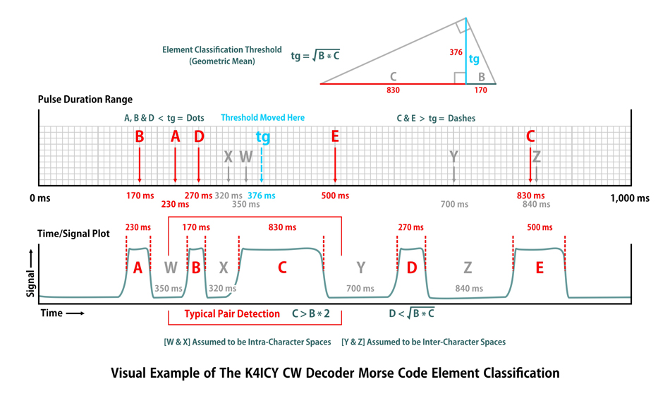
 Arduino Projects By Mike, K4ICY Arduino Projects By Mike, K4ICY Weekend Radio Click Here for More Electronics Projects and Tutorials By Mike Maynard, K4ICY K4ICY's CW Morse Decoder for Arduino This is an experimental WORK IN PROGRESS project - I can guarantee nothing. Download my current Schematic [below.] Download my current sketch [below.] Good at copying 35 word per minute code in your head? Nah... neither am I. With an Arduino, an LCD module and a few components you can have your own pocket-sized "secret decoder" that will do up to 80 wpm, enabling even you the "noob" to dive feet first into the CW bands with an electronic set of "swimmies!" While there are quite a few standalone Morse Code or CW decoders out there, I wanted to tackle the problem myself and end up with both a great Arduino learning project and a decent portable decoder for when I'm out in the field operating QRP. Now, before we get into debate over the virtues of learning to "head copying," I must suggest that it is better to be on the air and copy badly than to be an arm chair listener copying perfectly. ANY help a ham can get - if it leads to a path of more activity and proficiency - is preferable. Don't get me wrong, because I can copy CW in my head at 15 WPM and can easily recognize characters and some small words up to 40, but ADHD is a 'you know what' and it would be nice to have some help with the mental gymnastics. You may have seen the many options for CW decoders readily available, either as a sketch you can freely download for your microcontroller dev board or some cheap overseas pre-built option even available on eBay for a little as $11. You have the computer software solutions that integrate with station management software like HRD. These will detect call signs, access the QRZ database and set up macros for quick contest keying for you. For you portable ops, there are even free apps for your smart phone. My offering isn't a competitor by any means or a unique solution, but just an academic exercise. If you like tinkering with electronics and Arduinos, and have the CW itch, then why not give this a try? Where was I going to start? I searched a bit on Google and YouTube for examples for any "Arduino CW decoder" project and found that there wasn't but a few unique options. Perhaps the task of decoding required fancier processing. By far, the most tried and used Arduino CW decoder project [was] found here: http://www.skovholm.com/ but since has been taken down. [You can CLICK HERE to visit an archived copy of the http://www.skovholm.com/cwdecoder page at The Wayback Machine] It used a variation of the Goertzel formula to detect the actual audio CW tone so you can hook your device right up to the radio with very minimal components, then it uses a look-up table to match characters to display them. Most YouTube videos for an Arduino CW decoder seem to use this sketch. The simplicity of a rudimentary DSP is this project's strong suit... however, with no overhead remaining after detection, it's ability to decode CW seemed very lacking. Another popular option is the Morseduino by Budd Churchward, WB7FHC, found at: http://wb7fhc.com/arduino-decoder-sketch.html , http://wb7fhc.com/m2-cw-decoder.html and on other various project sites. Budd's Arduino sketch has to be one of the best structured ones I've seen and it's got a cleaver option for automatically 'tuning in' the decode tone using the popular and classic LM567 Tone Decoder IC from Texas Instruments, which as you will see with my project should be vastly preferred over the on-board Goertzel DSP tone capture option. However, just like the the prior offering, (and I believe it's the same,) the method for decoding leaves something to be desired. I have to take my hat off to one or two other builders who pioneered their own methods using a more 'digital' approach which sees the CW tones as 1's and O's, but even they admit it's only ok with rigid electronic code in a non-noisy environment. So what's the preferred method of decoding CW? Surely the magic formula has been academically established since the days of yore. Well yes, to a degree. You should check out Loftur E. Jónasson, TF3LJ / VE2LJX's Arduino project at: https://sites.google.com/site/lofturj/14-machine-recognition-of-hand-sent-morse-code [His main site:https://sites.google.com/site/lofturj/] Loftur has to have one of the more intelligent approachs of all the AVR-based decoders but it has a major speed limitation. His work is based on the 1973 USAF computer science paper by Joel Arthur Guenther: https://apps.dtic.mil/sti/tr/pdf/AD0786492.pdf which establishes a computer learning approach based on a Bayesian distribution/classification algorithm. This method basically 'assumes' or predicts the results by mechanism of creating a particular 'fingerprint' of the code derived from accumulated histogram data, a form of 'computer learning'. By the way, this is the core method that the creator of the popular CW Skimmer used in developing his software, though he says his was perfected "after thousands of algorithms," (or rather, iterations.) It certainly works because Skimmer is able to see scores of simultaneous QSO's at once within one window of radio bandwidth, decoding them all with frightening accuracy. If you're into contesting, buy his software and rack up the CW contacts. 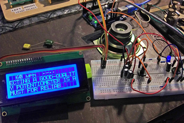 Shown here is my simple Arduino experimentation setup. The LCD connects with only 4 wires using I2C and you can see the simple tone detection circuity on the right. Madness to My Method After searching for ready-made solutions I loaded up a couple of representative sketches, wired the Arduino AVR board and tested each out. I took a look at one or two more offerings I found which were of the simpler type capable of running on an Arduino but the same 'dit'-'dah' (or Dot / Dash) element detection method was used, as per the description on one site, "the software tracks the speed of the sender's dahs to make its adjustments. The more dahs you send at the beginning the sooner it locks into solid copy." The method in use with their decoder works by basing a moving average threshold set in relation to what it detects as the dashes. A dot is detected by seeing if an incoming pulse is {less than half} of a moving average of the dash duration. Inter- and intra-character spacing is also considered. My eventual primary method [which was created before even studying theirs,] has one or two similarities in the approach, but theirs has a few shortcomings, namely, that it's pretty much trying to decipher code at a Dot/Dash ratio of 1:3 and also a very slow recovery when an operator's code element weight ratios or sending speed changes. I'm not knocking anyone else's solution, as it's surely a winner for the Arduino platform, but after a few trial runs I realized that sometimes this algorithm had problems knowing when the 'dah's changed in duration and sometimes it either took a slough of characters to lock in again or wouldn't lock at all. This was all very unforgiving for hand-sent code. I remember tapping our the letter "V" over and over to no avail. And what's it with the occasional crashing? Even the author suggested pressing reset if the Arduino locked up. The crashing was most likely due to interrupts colliding with integral timers while trying to access memory pointers. The Morseduino sketch is well designed and addresses a few pitfalls including contact bouncing via delay timing. The sketch using the Goertzel tone-detection formula suffered for the reason that the ATmega328p 8-bit microcontroller on the Arduino simply lacks the horsepower to handle both a Fourier transform for DSP as well as any critical timing event tracking simultaneously and I found it struggling to decipher even 15 WPM code. As a concession, I think an experimenter could use two Arduinos or a faster ESP-type multi-core platform to enjoy better results from an otherwise decent sketch. What would I learn or gain by settling with someone else's Arduino sketch? I didn't want to just outright adopt their decoder algorithm, plus, thousands of hams have already enjoyed the ease of just uploading their sketches, because they (kinda) worked. I wanted to figure something out from scratch so that I could understand it all myself, even if I ended up with the same solution. I did consider the absurdity of reinventing a well-tried wheel and that surely, there were mathematicians and computer scientists who could site a textbook formulae at whim, using "tensor integrals" or "adversarial Bayesian probability discrimination networks" [add jargon...] at seemingly un-quantifiable human-based code and surely see easy success. You know what they say: "cum autem probationem solvitur - quod erat demonstrandum!" An elegant solution was just on the tip of my tongue and I couldn't quite figure it out! Like Einstein, Maxwell and Tesla, I often practice the mental astral projection exercise of the thought experiment. [Did I just compare myself to Tesla?] Instead of studying how these other decoders 'saw' the pulses, I spent a few cool late spring nights, [all night and during the Covid-19 lock down,] standing out in my front driveway under the stars conjuring plausible solutions to discriminate CW hand-sent pulses. I couldn't quite put two and two together at first and found myself continually deep in thought, even for a few days as I was stuck in another hangup as to what method might work better or not. The late Jean Shepherd of "The Christmas Story" fame once spun a story about such a hangup. He was a ham, you know, and he spoke about building a homebrew rig as a teen, "this way lies madness, this way lies the antisocial animal and once you've committed yourself to the antisocial animal, forever you'll be down in some dank basement surrounded by half-empty Ball jars full of nails, and the rest of your life will be given over to this insanity, I knew that even then (as an animal) that hangups can devour you!" To my rescue though, the solution struck me one morning as I awoke... I would go through several attempts at a working algorithm, addressing deficiencies and incorporating enhancements. I had to deal with the real limitations to the speed and power of the Atmega328p microcontroller chip. I could've stepped up, but more hams would benefit from getting into this ground-floor Arduino offering. I often found that when I rewrote a section of the sketch or added some line of code, or some variable, the speed and accuracy of my decoder was reduced, leaving me to do a lot of trial and error, and some compromise through actual practice and experimentation. The algorithm that I'm currently satisfied with works like this; Morse code is generally sent with the duration of the Dots and Dashes pulses being at a 1:3 ratio, but this can greatly vary depending on the operator's 'hand' or the timing device, and with hand-sent code the timing can vary even within a single character. This seeming randomness can be hard to nail down, but there should be evident pattern. First, we capture the duration of each incoming pulse as well as the off-time (or Space,) and we also retain the duration of the prior pulse. With these two durations we can see if one is longer than the other but by some reference factor, like a ratio of 2:1. If an apparent dissimilar pair is found , then it can be assumed that we have a current representation of the code's timing, and since any presumed pair of evidently different pulse durations are consecutive to each other, it can then be assumed that the word-per-minute timing will be the same. It's so simple when you think about it! How does the ear and mind know when a short and long pulse have been sent together, even if the actual timing is variable and uneven? They know because one pulse is obviously longer or shorter than the other. To understand what I have set up you should further study the Arduino sketch .ino. Next, a classification threshold is established which is used to discriminate any relevant future Dot or Dash pulse durations. A geometric mean is derived from the moving mean averages of the Dots and Dashes as found in pairs, which is based on the square root of the product of the two range durations. This threshold is used to classify or discriminate between any further pulse durations to determine whether or not they are also a Dot or a Dash. Just having two consecutive pulse elements different by some comparison isn't enough to establish a code foundation, there needs to be enough established consistency. I found that a threshold using the geometric mean tended to yield more accurate decode results over using an arithmetic mean (plain mid-point average,) whereas the threshold is held closer (but in proportion) to the duration value of the the Dot rather than the Dash. This makes sense, as the shorter Dot elements tend to remain shorter but had the most proportional length variation, and in kind, the longer Dash tended towards being larger, but were more consistent compared to the variation of the Dots. You can see this tendency in the distribution shown in the diagram below; durations [A, B and D] appear to be Dots and [C] appears to most likely be a Dash. [E] is a close call but would certainly sound like a Dash if played in tonal sequence with [A or B.] The thresholds are continually reevaluated, with each new found Dot/Dash pair, and altered gradually through a moving average. A detection is in place for thresholds that lie outside of any established pair ranges. This way, quick corrective adjustments can be made. The spacing between code elements, between code character and words as well are also considered using this threshold. Moving averages are kept for both captured durations of each Dot and Dash found in pairs, as well as the spaces. The downside is that it takes longer for the decoder to "lock in" which can be between 2 and 20 characters. Lock-In results are closer to the low end and I've been able to decode computer-sent code accurately at 60 wpm, and even as high as 85 wpm with an expected amount of error. Hand-sent code is copied quite well [compared to other methods,] and as you would expect, the better the "fist" of the sender, the better the copy. Sloppy code shows and can throw off the algorithm for a bit but it does find its way back to lock. The word per minute count, or WPM is calculated by dividing the sum of the dot, the dash and the in-between space [which makes 5 theoretical "PARIS" time units] into 6,000. WPM calculation is not an exact science and hand-sent code can really throw the math off but it's a useful number to know so that you can match you keyer's sending speed to that of the other operator. How effective is my approach? By the way, the above hypotheticals shown in the threshold example chart would equal 4 WPM (lol)... yes, it can detect QRS as well as QRQ. The use of histogram-based machine learning is obviously going to be a preferred method which only gets better as more characters are sent from any particular sender, but again, my method is a practical solution for a budget microcontroller and may even be an applicable solution for mechanical or discrete electronics methods... in theory. That would be insanely complex. The Works The first requirement of a CW decoder is to convert the audio containing the Morse code to a logic-level signal; on or off. I have experience with the LM567 Tone Decoder IC when I played around with making a Zero-Beat Indicator for CW. The chip works spot-on as long as you use good components to resist PLL-lock VCO drifting. The 567 is able to pick out even lower volume tones (matching it's VCO) even within a pileup. The ability of a CW decoder to work has to be done in two separate parts; the ability to discriminate a tone and turn it into an boolean electronic signal, and the ability to decode the signal. A Warning on Performance: The quality of the decoded intelligence will never be better than the input signal you give it! Even though the decoder can translate at nearly 80 wpm with perfect computer created code doesn't mean that you'll get legible text at even 20 wpm from a real on-air signal from your radio. Some of the factors working against a clean decode includes adjacent signal interference (QRM) from other close by CW signals, atmospheric noise (QRN) including spurious lightning splatters, fading (QSB), other sources of interference from wi-fi and electrical service, and last but not least, audio distortion including ringing, imaging and so forth. Both the LM567 Tone Decoder IC as well as a basic Goertzel Forier-based DSP will suffer the same problem of reacting from matching resonant and harmonic audio energy signatures, so the more noise you have, the more false positives or negatives you'll have. You can only do better with broadband "fingerprint" methods of DSP. There are some steps that can be implemented electronically before feeding the signal into the Arduino for decoding. Many of these steps can be implemented in a modern radio, and more particularly a DSP transceiver. 1) Use a DSP-based noise reduction filter. There are also traditional schemes for broad-spectrum noise reduction. 2) Then pass the signal, which should now have more intelligible CW tones present, through an active bandpass filter. You can try [this one here.] 3) Then, you should amplify the signal to adjust for previous filter loss and to set the level for adequate response at the LM567 decoder IC. Automatic gain control (AGC) is not required but will mitigate fading (QSB). 4) Use the LM567 tone decoder, considering any discrete component value adjustments for optimum response. Try using another Arduino with a Goertzel decoder sketch. Without the overhead of a decoder program you may be able to employ a higher-level detection algorithm. 5) Finally, as additional CW signals, crackle or pops may have been carried through, a (hardware) debouncing circuit should be used. This usually includes a small-value capacitor, a resistor and a buffer gate (any Schmitt trigger logic) with some hysteresis in the logic levels. Again, your radio may come with some built-in filters where you can reduce the bandpass "skirt" envelope, use some level of noise reduction, adjust the IF pass, volume, RF input level or anything that you can do on the radio's end and see if you are able to get a cleaner decode. In the future, I plan on coming up with some circuit variation (including the LM567 circuit shown below), and I may also get an FFT discriminator project working for an ATTiny85, which I'll share here. If you wish to learn a bit more about the LMS567 Tone Discriminator, you can follow Matt Roberts, KK5JY's example circuit at: http://www.kk5jy.net/cw-modem-v1/ Matt has put some effort into getting a quality result from the 567 and all I would suggest adding is some variety of audio bandpass filtering, perhaps with and OP am like the LM741, maybe set for some gain with a little bandpass filtering in multiple stages to further help the 567. If your CW tone signal is not OPTIMALLY detected and passed on by your 567 circuit the CW Decoder will have trouble registering the pulses properly and thus will not decode without much error. If you see a lot of character garbage or excessive "E"s the FIRST troubleshooting path you should take is to FINE TUNE the 567 potentiometer and adjust the input audio gain. You can build the pre-567 audio filter, (maybe just the first stage,) by following my example project here: cw_decoder.html The second requirement is the decoder sketch running on an Arduino. So follow along if you can: • A time reference is continually updated using the millis() function. • Poll a digital input pin to know when a Morse key or the output from a tone decoder is active. • Debounce the pin using a small time delay to reduce any spurious signal noise. • Keep track of the duration of any pulse (key-down and key-up) and retain the previous duration detected as a reference. • A range pair is found when one pulse (in any order) is, by some multiple (2 times that) of the other. • The two durations, assumed to be a Dot and a Dash are kept within a moving average (to resist wild fluctuations.) • Discriminator reference threshold point is established via a geometric mean and any further Dots or Dashes are determined by this threshold. • Bootstrapping: Move the thresholds instantly to the center if it is obvious that they reside outside the range. This can readjust or match speed in as little as ONE decoded character generally only printing a handful of "T" / "E" false positives. • Thresholds are readjusted, as need be, with each new Dot/Dash pair in consideration. • Any further detected pulse is distributed by duration ( < or > ) according to the geometric threshold point. This gives you the "-" or ".". which is added to a String for decoding. • Using the same threshold as a reference, a space (off period recoded) after an element that is less than ( < ) the threshold can be considered an intra-character space (between the elements.) • A space greater than ( > ) that threshold, but less than ( < ) the average duration of the Dash is indication that the character code is complete and can now be translated. • A space larger than the duration of the average Dash can be considered to be a space character ( " " ) or a Word space. • A lookup table or IF statement list is then used to match the decoded element set, i.e.: "- - . -", to the appropriate character ( = "Q" ). • We can print the decoded character to an LCD panel. • WPM (Word Per Minute) is a generalized metric based on the established timing of the word "PARIS" including its proper spacing and elements. We can add the moving averages of the measured Dots, Dashes and integral intra-element spaces for dividing the sum into 1 minute. ( 6,000 / (Dot + Space + Dash) ) The is actually a better measurement of Characters per minute than Words per minute. A small factor can be applied to the derived WPM to compensate for processing and timing lags. • Any other implementations are for creature comfort and up to the available processing power of the microcontroller, not compromising on decode accuracy. The Plan I give to you, the prospective builder, a copy of my [current] Arduino sketch to experiment with, make use, tweak, change or otherwise just enjoy. I make no claim that my crude method is any better than the 'dah' reference method of the other methods and holds no candle light to the blinding radiance of the PC-based Bayesian algorithms, but as, with any homebrew ham or Arduino project, this is more educational if anything else. The LICENSE for the Arduino sketch is as follows: You are allowed to alter, improve and redistribute the code (.ino sketch) and can use in any capacity within your personal builds and experiments, but you must retain and give credit to Michael A. Maynard, K4ICY, the author in the redistributed code and any journal or web site blog or entry. AMY use (including any specific method exclusive to this author) in a commercial product, such as a kit, requires that the seller and/or manufacture yield a royalty of at least 15% of the retail price. Suggestions, or rather helpful fixes are gladly appreciated. You can download my current sketch here [K4ICY's CW Decoder - Version: 1.14r 06/23/20] : : : k4icy_cw_decoder_14r.ino This is the most stable sketch I have up to this posting and will have a bit more tweaking for performance and added features IF ALLOWABLE. I need to state that it is not perfect and there are compromises, but my goal was to produce something elegant and deceptively simple which could be built and thrown into any ham's QRP go-kit. I would like to use a cheap phone charge battery pack and include everything inside of a compact weatherproof enclosure. I have a lot of real world testing left to do and I'm not quite satisfied with all the nuances. Program Considerations One would be forgiven to think it would be easy to engineer an elegant and properly formatted sketch that was as robust and bluntly rudimentary as designing a hammer or toaster. Due to the expected limitations of the basic Arduino's ATmega328p AVR chip for speed and processing power and the manifold overhead from running the higher abstract layers of Arduino IDE C++, decoding the nuanced timing of CW, whether hand-sent or electronic (with a lower expectation for hand-sent code, considering,) and at speeds up through my desired limit of 60 wpm, is a feat to be satisfied with. The timing seems to start breaking down around 65 wpm and is completely disrupted by 80 wpm. The sketch was always in need of tweaking and compromise contingency programming, for example; adding fixes to one part, especially dealing with LCD output, would break other parts and adding more code naturally slows down the resolution of the pulse readings, or using a for loop to preform a repetitive process can actually take up more cycles to perform than actually using a repetitive list in the sketch. I've also chosen to use a fixed LCD panel type of 20 x 4 characters which is controlled by the I2C interface. There are sections of the code that need to be re-written, parts made into functions and other measures tried. Under testing, this CW decoder has (almost) worked perfectly with computer-sent code of up to 80 WPM. Hand-sent code at slower speeds, around 18 where I could send, was fine for the most part but some characters wouldn't be seen until I sent another few characters with good short-long element pairs. I'm welcome to collaborative tweaks and suggestions, but just try it for yourself for curiosity's sake. Eventually, I'll look into working on the timer level, using ISR's to capture inputs as well as converting the inefficient character string / IF statement-based lookup decoder with a Huffman-like decoder tree. Again, porting the sketch to an ESP32 would make any considered optimizations needless, but I would like to keep this simple enough for anyone with an old school Arduino UNO R3 to end up with a happy weekend radio project. Considering the other direction, could the sketch be run on an ATTiny85? If the Tiny was 16mHz crystal driven, leaving two pins for I2C for the LCD and 1 pin for the input, it could be possible if the running sketch fits within 8k bytes. Electronics 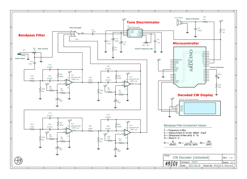 You can download my current schematic as a PDF here [K4ICY's CW Decoder - Version: 1.14r.1a 06/30/21] : : : Media Fire Folder A HUGE DISCLAIMER! ::: I can't count the number of emails I received from builders who critique the bandpass filter part of the circuit, some even giving me math discourses, correcting my R/C values. Please consider the op-amp filter circuit to be academic ONLY. The only reason for this project was to find a solution of the decoder, not the discriminator. The is not a product, just an example. I have no firm plan on where I'll take my circuit design for the decoder. Do I place a ATmega328P DIP package and crystal on a proto-board with the LM567 and what other types of circuits for signal conditioning and battery management should I include, particularly something that doesn't dwarf the microcontroller's job, so to speak? Should I use a Nano? The code is too large [as it is] for an ATTiny85. Is there a small DSP chip used for weeding tonal ranges out of audio signals. You EQ lightshow guys should know... So far, the above schematic [as is, by whole] was only bench tested, and the major experiments were done with just the Tone Discriminator IC portion connected to the audio-out from a PC. A 4-section very narrow audio bandpass filter was added BY REQUEST. I recycled this from my CW Filter Circuit [Here] which really packs a punch and will isolate your chosen frequency range down to a few dozen Hz with expectant harmonic ringing. Each op-amp stage is redundant but can be offset if needed, and is chained in a selectable sequence via rotary switch to suit for reception conditions. For your chosen center frequency you'll have to calculate for the components of the Twin-T RC networks and will not be variable unless you plan on using some kind of super-fancy ganged potentiometer array. The major issue you may have will be with audio coupling between the different sections from your rig to the discriminator. Keep the lead lengths short and components close on this one. The Tone Discriminator will have to be carefully tuned to match. It is a MUST that you use only a high-quality multi-turn pot which is rated for low thermal drift. When building, Start with the Arduino and the sketch. Connect a straight key to the input pin along with a debouncing cap (0.01uF) to ground and an actual pull-up resistor which also drains the cap as the internal AVC pull-up is high-impedance. The Decoder should work well with your hand-sent code and is actually fun with this setup. Next, work on getting the Tone Discriminator to work. Feed in the audio from your rig with the key down, set to produce a practice sidetone only, and with no static or noise. Tweak RP2 for optimum detection. You should connect an LED and current-limiting resistor to the OUT pin (8) of the IC. A good digital signal here is a good signal for the Arduino sketch input. Do some experimenting receiving real-world CW signals. Working with the op-amps will be tricky for the beginner, but the simplest method without a signal generator and spectrum analyzer is to download a fixed tone maker app for your smartphone and listen to the output of one Op-amp with headphones. Sweep through a range of frequencies and note the loudness. This should give you some clue as to how to adjust the resistor values. Just see the math on the schematic. Keep the caps at an easy round value as resistance is easier to adjust. Below, is a list of some of the major parts. I left the pinout code for a standard LCD interface in the sketch if you wish to go that route. I went with the I2C method just for the novelty factor. This should be such a common Saturday ham radio project these days and my version most likely has nothing unique to add. I'll leave that to you. Major Parts: • Arduino Nano $8 • 20 x 4 "2004" Character LCD Display w/ I2C Interface $10 • LM567 Tone Decode IC, 8-pin DIP (TI) $2 THIS WIRING SCHEMATIC IS CURRENTLY EXPERIMENTAL! . Take It Or Leave It - It's Worth Experimenting With Of the handful of projects posted on K4ICY.com, this one has had an odd response. I've fielded more than a few emails since I've published this page that I would say, were a little less than praiseworthy, which doesn't represent the majority. The majority of these were insistent inquiries into a schematic for an interface which would send their QRM-riddled CW audio signals into the Arduino to be beautifully processed just like with the CW Skimmer. The primary point of this project was an academic approach on a microcontroller program that could tackle the task of decoding CW, not to figure out an interface and make a commercial product. Good products take the hands and time of many engineers and specialists and the capital of a corporation. I eventually caved a little and drew up a schematic using my CW filter project, which was not even a great one, but of this, I've received a handful of 'instructive' correspondences from apparently engineer-level hams who seemed fit to critique my op-amp filter parameters, a few with much fervor. I've no plans to update this circuit, by the way, so it is what it is. I don't mind helpful electronics education but keep in mind that I'm not a university student and this isn't a paper for peer review. Ham radio is all for fun, right? (outside of public safety obligations), and building projects brings so much of it, so I enjoy sharing all of it. But go easy on us who do share. This also goes for people getting mad at me for not keeping my site links current. Really? For that, you may try the Wayback Machine from Archive.org. Then again, I've also been chewed out by a woman for not continuously exuding staunch "professionalism" as those within amateur radio must always. The miserable often rear their ugly heads. [...Stepping down from my soap box now.] Well? If you have a working open-source solution for the filter/tone discriminator end you would like to share, then I'll gladly post it here along with credit. It's certainly fair that any ham with CW interests would look for an all-in-one solution in their desire to forgo the cost of buying a commercial product, and maybe even garner some Arduino experience. I've nothing against helpful criticism but since this isn't my day job... At the VERY LEAST load the sketch up and connect a key to the input [in lieu of the line coming from the tone decoder IC] and enjoy honing your sending skills with good feedback. . User Experience A huge reason why I post these build journals it to share my experience figuring stuff out with a hope that other curious folks would take what they've discovered here and run with it. I certainly do appreciate the more gracious correspondences and yes, I'm glad to offer kind advice, especially to the electronics/homebrewing noobs and if you've tried your hand at the decoder with some success, please tell me about it and I'll be glad to post your construction pics! . The Arduino CW Morse Decoder by Jorge, AB6WP: Jorge took on my decoder project with great enthusiasm building a homebrew tone decoder and filter circuit (with his choice of op-amps,) along with an Arduino, and housing everything in a nice case. He's new to Arduino and his build has given him a bit of experience and a great example of adding MCU's to the ham radio electronics universe. Check out the pics: . 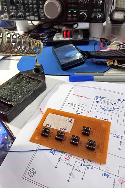
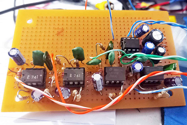
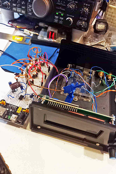
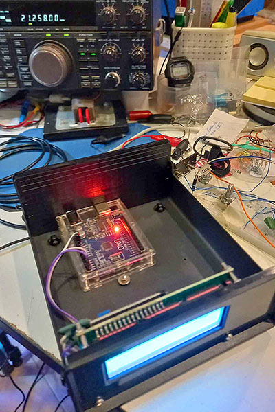
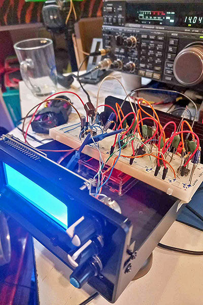
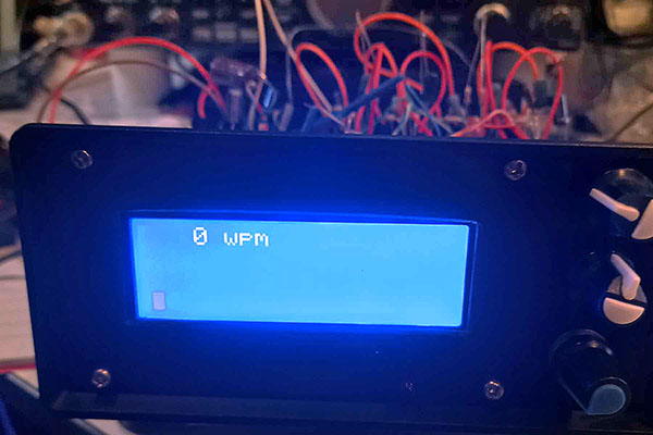
. ...Ready for Decoding... . Contact me at mikek4icy@gmail.com 73 DE MIKE K4ICY Updated
06/30/21, 10/17/23, 12/18/24
|
