Weekend Radio Click Here for More Electronics Projects and Tutorials By Mike Maynard, K4ICY The Depot Cootie Key - An Easy-to-Build Single-Lever Morse Paddle As Presented in The Printed Circuit, Newsletter of the Tallahassee Amateur Radio Society (TARS). January 2015 - Page 13 Click Here for an index of Electronics Projects _ Check
this beautiful Depot Cootie Key build by Mark W. Allendorf, KM4AHP! Build Your Own “Depot Cootie” Key for as Little as $10! _
left and
right. Many a new ham of not-so-prosperous times found the
"Cootie" to be an economic necessity for enjoying their new Novice
licenses. As the early part of the 20th century rolled on,
hams found themselves converting surplus or broken semi-automatic "Bug"
keys to single-lever paddles. Later on, with the advent of
the transistor age, when electronic keying became an affordable
reality, a few enterprising key manufacturers produced dedicated solid
arm models which promised incredible speeds and improved sending
accuracy. A few particular models are still in production
today and are considered popular and the key of choice for speed
aficionados.
_  Check out Mike Aiello, N2HTT's very well done Depot Cootie, and read his fantastic article on Cootie keys! http://www.ll-leasing.com/pcara/docs/pcud0217.pdf#page=5 _ "Can I build one for myself so easily?" you say. Yes, and I'll show you an example that took me only half an hour to build and it works great! Throuout this page you'll also find many great examples by many hams that followed along and 'rolled their own'. There's a beauty in constructing something with simple parts. First of all, we need to do a little "up-cycling" by re-using an old part that would have normally gone to the landfill. Go take a look at your hacksaw, in particular, the type used for cutting light metal or wood and has a thin blade that is at least a foot long (30cm) and 1/2” (13mm) wide - this is the main part we’ll need. If you don't have one lying around, that's okay, a pack of replacement blades are not that expensive. You may also be able to find other applicable pieces of spring steel at your local hardware store. You'll need to do a little prep to the blade once you have your other parts, so keep these old and worn blades handy for future “gift” keys. _
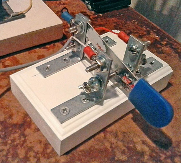
Once affixed to the base, the bottom holes on the vertical section are used to mount the blade and the contacts while the top holes serve to connect the wires. You'll see that the list of fasteners is a little extensive including two kinds of lock washers and pan-head machine screws, but nothing here is critical and I leave it up to you to figure out a solution that works best for you. Just be innovative and experiment. The one part that may be important is to use all #8 fastener sizes as we'll discuss later. Also, everything should be stainless steel if you can get it so that your key will not suffer from poor electrical connections later on due to surface oxidation. Brass parts may be fine but they will need cleaning once and a while. _
HARDWARE: Steel ˝” (13mm) Hacksaw Blade, Pre-Cut 4-1/2” x 2-3/4“ x 1” (12cm x 7cm x 2.5cm) (not critical) Fiberboard Trim Block, (4) 1-1/2” (1/2“ wide) (38mm) Galvanized Corner Braces (Brass or "faux-brass" hardware may contain a non-conductive coating), (3) #8-32 x 5/8” Pan (or round) Head Machine Screws, (2) #8-32 x 1” Pan (or round) Head Machine Screws, (6) #8-32 Machine Screw Nuts, (6) #8 Ext. Tooth (Star) Lock Washers, (6) #8 Flat Washers, (6) #8 Med. Split Lock Washers, (2) #8-32 Wing Nuts, [Use whatever 4mm+ metric sizes that will suit,] (4) Small Adhesive-Back Rubber Feet, Finger Piece taken from a Chip-Clip – or use anything you personally prefer that can be glued on. _  An attractive build from Mark Steele, KD2NOM! - [I like the angled swing arm aspect!] _ TOOLS: Large Tin Snips (Metal Shears), Drill (for pilot holes in wood), Screwdrivers, Socket Drivers, Metal File, (opt.) J.B. Weld
For a better method, I suggest using a nylon-insert lock nut permanently attached to the corner brace using J.B. Weld® epoxy resin. You can also "Weld" the wing nut to the pan-head end of the machine screw which will give you a precise adjustment mechanism - just make sure there is good electrical conductivity along some part of the screw. You can also “Weld” the contact-side nut to the brace and leave the wing nut free to act as a stop nut. Like I said: nothing critical here - just use your imagination. _
_
_ 7)
Attach
some small adhesive-back rubber feet to
the bottom of the base. This
key will be
too light by itself to operate without sliding around on the table, so
rubber
feet will help. Using
a sheet of soft
high-friction silicone adhered to the entire bottom surface of the base
will be
better. You can
also attach it to a
larger piece of wood or to the table itself! 8) Attach the key's wires either by wrapping the wire around the screws and then clamped down in between two washers held in place by a nut or solder terminal lugs on to the wire and clamp the lugs to the top positions on the corner braces as shown. _  A very fine build from Dr. Avi Rochman, 4X1WQ! - [Note the subtle design improvement?] _ Adjustment should be straight forward - the gap between the end of each contact screw and the blade surface should be set for best comfort. The Cootie key can not only be used for side-swipe sending but to command an "iambic" automatic keyer, each paddle contact for the 'dit' and 'dah' circuit respectively. If you are using a keyer then you may want extremely tight spacing. As you can see in my example, I added a second blade from the top screw position, angled down to the finger piece. I did this to effectively double the "spring" tension because I needed more resistance in moving the arm a very minute distance at only 0.005", just the thickness of a sheet of paper. _  A Classic Example from Jeremy Wirtz, AA4JW _ Single-lever control of an automatic keyer is not the same in operation as with a dual-lever paddle where "squeezing" achieves the desired result of an automatic "iambic" pattern of alternating 'dits' and 'dahs'. You have to manually alternate between each 'dit' and 'dah' contact to achieve this pattern and your timing has to be close enough so that you don't end up getting unintended elements. I would suggest operating in "Iambic Mode B" so an extra element can be added to save on timing. There are some advantages though as this approach is claimed to operate a keyer with fewer errors in sending. Many find the single-lever key easier to learn which is why it is perhaps a "best seller" by a certain key manufacturer over their other products. _  _ Now to talk a bit about using the Cootie key in its intended fashion: which is to send code by the “side-swiping” method. For one of many instructional YouTube videos visit this link: https://www.youtube.com/watch?v=ZfLrgYHIpjo (An introduction to the Sideswiper) In sides-swiping 'dits' and 'dahs' are produced manually as with a straight key, but in succession of moving the arm from one contact to the other. As by common practice, elements are always started by moving the paddle from right to left – where the left contact is always made first - then alternately keying between each opposing contact until the character is completed, starting again with each new character. The left contact is always keyed first regardless of character. This method of sending is claimed to be "the hardest" to learn of all keys, but once the user has become more practiced at it, side-swiping becomes one of the most comfortable! _  Even better! Dennis P. Stahr, K6DS's Cootie uses a metal ruler... a clean look! _ The adjustment of a Cootie key (or single-lever paddle) used in side-swiping differs from that of electronic keying. The "weighting" of the side-swiped elements tends to be “heavier,” which to those that don't know, weighting is the term used to express the timing ratio between the marks (on) and spaces (off) of a character element. A repeated keyer ‘dit’ is generally set to a 1:1 ratio and you should get a "dit dit dit" sound, but in sideswiping, you're more likely to get a "diidiidit" sound which is one reason why side-swiping has such a characteristic sound on the air. To alleviate the propensity for heavy weighting, it is generally better to set the contacts very wide apart so that your wrist has to take more time to move the key arm from one contact to the other - maybe up to a 1/4" gap. Don't fear side-swiping, just give it a good College try for yourself. _  Enjoying his new found love for Ham Radio and CW: Richard, M7MYR, takes to the air waves with his new Foundation license, new FT-818 and his trusty homebrew Cootie! If you've built your own Cootie key then congratulations and welcome to the club! Homebrewing hams are a sparce commodity compared to days of old, not to mention CW operators for that matter. And if you're a side-swiper (like myself) then truly, you are a rare find. Feel free to contact me at: mikek4icy@gmail.com One more thing... If you build one yourself, I'll be more than happy to post a pic and even a link here! 73! DE Mike, K4ICY _
The "Minimum-Metal Warm-Wood Cootie" (MMWW) by Stan Vause, ZL3TK Body pieces are varnished 12 mm plywood, the swing arm is a piece of PVC cut from a discarded road-edge marker, angle brackets were cut from scrap aluminum, all hardware is stainless steel from salvaged thrown-out home appliances, and the small, u-shaped brass common-contact is glued to the main arm. Thin-gauge wiring is hidden in grooves, one beneath the PVC main arm and two beneath the plywood base, ergo, "minimum metal." Cost: virtually free.
Discovering the joy of homebrewing _by John Alcock, AD9CB
Homemade by KB5RCF _
Very Classy in Black _
A Fine Example by Mark W. Allendorf, KM4AHP built for only $12 usd! _
Manoel Lopes's Mini Cootie Key _  Luis Alvarez's Depot Cootie _
Edited: 12/27/24
|


 Cootie")


