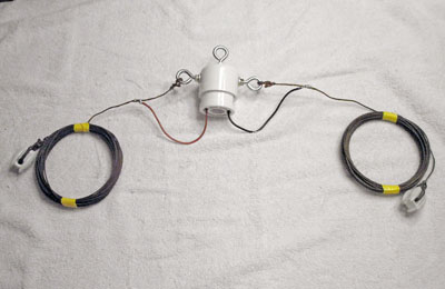
The "Cylinder" - Super-Tough Center Connector for Dipole Antenna
This is yet another alternative homebrew center connector for a wire dipole HF antenna. Yes, commercially available versions are cheap and easy, and you can make one out of a scrap piece of Plexiglass (R) but why not make a weather-proof one out of your scrap junk or cheap material from the home improvement store. This one will fit my requirements for a simple 40m wire dipole or inverted-V and will be compact, waterproof, fairly durable, plus has room for a current BALUN. - This will only cost about $12 in materials!
The construction difficulty is fairly
moderate as it will only
require some slightly precise drilling into the Schedule-40 PVC.
The
parts used are common PVC accessories found at the home supply store.
This one will hold much more weight than the connector end of
the feed
line could hold, but of course, no guarantees and the builder assumes
all responsibility.
PVC pipe
connectors are to be used. No weak length-pipe will be included.
(Click
to enlarge photos)
Parts to be used:
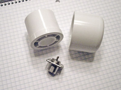
1 - PVC End Cap, 1-1/2"
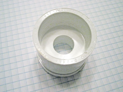
1 - PVC Reducer, 1-1/2" Pipe
Diameter external body to 1/2" adapter
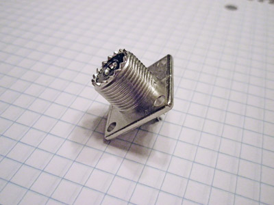
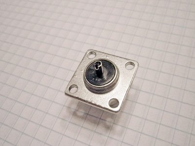
1 - SO-239 UHF Flange Mount
Female Socket. Four mount holes in square flange.
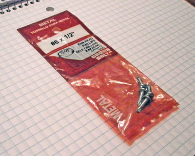
1 - Screws, Pan Head Sheet
Metal, #6 x 1/2" (or down to 1/4") Stainless if possible.
3 - Eye Bolts, Closed Loop,
Bolt End 3/16" x 2" plus nylon lock washers or bolts, bolts, x 2 disc
washers, lock washers. Course or Fine threaded, Stainless where
available.
10-14 gauge wire for connections.
PVC pipe cleaning fluid and cement.
Silicone long life weather proofing sealant.
The Flange Mount UHF SO-239 Connector.
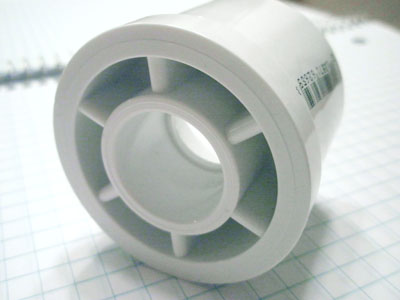
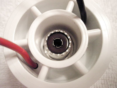
The PVC reducer adapter. Perfectly made for housing the connector and providing a water shroud for the coax lead.
These four screws will hold the connector into the adapter.
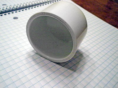
Cover Cap. Can be
adjusted for internal space and total body height. Enough space for a
toridal current balun assembly.
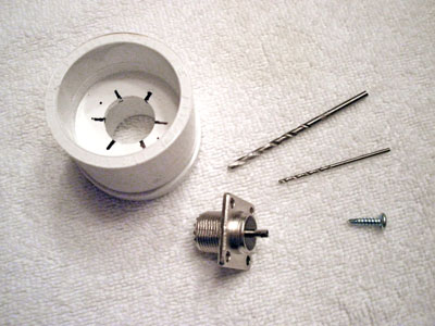
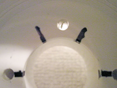
A starter drill bit, a finisher of the size to snuggly accept the screws and a size to accept you connector wire.
Basically, mark the exact locations and drill holes.
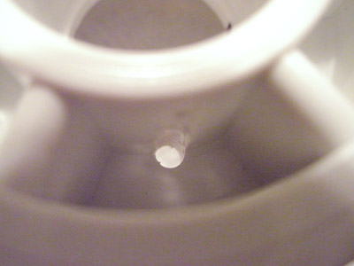
There are these support ridges on the
bottom of the part. I
drilled exactly into the middle of two and the two remaining were drill
along the outside wall of the 1/2" pipe socket and used a magic marker
to make my drilling locations by using the part itself as a template.
PVC is almost as easy as wood to drill into and I used a hand-held
power drill. Though, I do suggest using a drill press to make
perfectly straight bores.
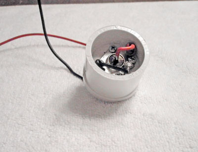
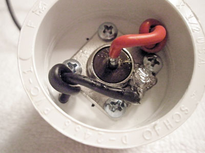
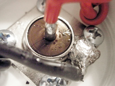
Mounted UHF connector with hook-up leads routed through. I'm glad that Soldering was not on the Extra exam! It did not help that the soldering gun tip broke down.
When the holes were finished I then cut
a foot each of two lengths
of multi-strand wire. If you are using up to 300 watts of PEP from you
transmitter, #14 gauge should do fine. Solder the wires to
the UHF
connector after tinning the ends. I suggest using some type of lug
connector placed under one of the screws with a little of that special
grease that keeps contacts from loosing their conductivity due to
weather. My soldering gun's tip finally gave out and I made due,
thought the connection seems sturdy and conducts well, it sure looks
ugly! Well, it's getting covered anyway. Screw the UHF connector into
the PVC part and route the wires through their holes, tying a knot in
each first to keep them from being pulled off the connector In case a
tree limb pays a visit during a storm. Now is a good time to seal the
deal with some weather sealant to keep the moisture out.
Well, looks good on the outside! We now have a housing for our connector that provide excellent rain protection.
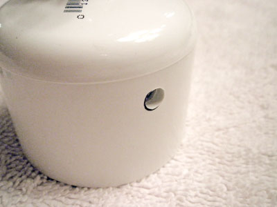
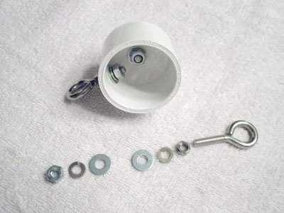
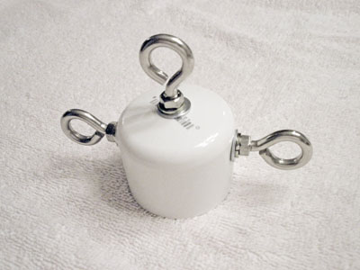
Into the top and top-side of the PVC end cap go the three eye bolts, two for the antenna elements and the center for anchoring.
Holes
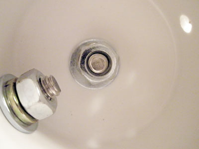
drilled into the cap, and hardware installed.
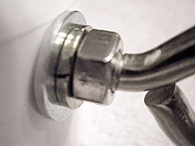
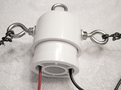
I used 1/4" thread x 2" long stainless steel eye-bolts and additional stainless or zinc-plated hardware and used two sizes of drill bits. One bit was for the minimum clearance for the inner part of the thread cut. That way, I had to screw the eye-bolts into place, meaning that the threads were very securely fassened inside the PVC plastic to resist water. I used a larger bit to allow for setting the bolt end. I drilled a hole in the center on top of the PVC cap and for the sides, I found my locations for drilling by placing the washer at the edge of the factory seam on the cap, as shown above. Inside, for tightening the bolts, I used a combination of two wrenches and a socket wrench. Always use either lock-washers, split-lock-washers, nylon lock nuts or a dab of Loc-Tite sealant. Or they will come loose over time. Align them for up and down movement.
After
cementing the two halves together, the dipole wires are tied to the
hooks and the leads are soldered to them.
Not
shown: the two PVC parts are cleaned with PVC cleaner at the joints and
cemented together with heavy duty PVC cement. Air has to escape when
combining, so hold parts together for at least half a minute. Tie the
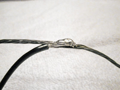
dipole wires to the post with any good means, either by a decent
mariner's knot, a clamp or lots of twisting. If soldering,
you'll have
to use a good soldering gun with at least 150 watts, unlike mine that
has a few glitches in it. The leads from the connector should be added
to the total cut length for resonance on the dipole. Just add a little Coax-Seal™
or Rescue Tape™ to your feed line cable end
connector and you're good to go!
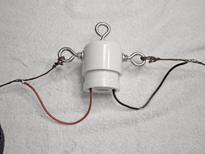
Finalized
dipole antenna using new weather-proof connector ready to install.
Not bad
for $11.50! Cheaper than the cheap one from MFJ, and without the
shipping over-charge!
Should withstand the most from rain, wind, bird roost and bear attack!
Edited:
06/26/20
(c)2020 Copyright - Michael A. Maynard, a.k.a. K4ICY
