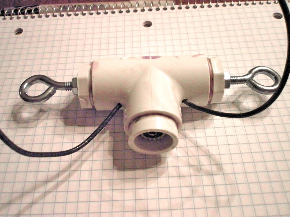
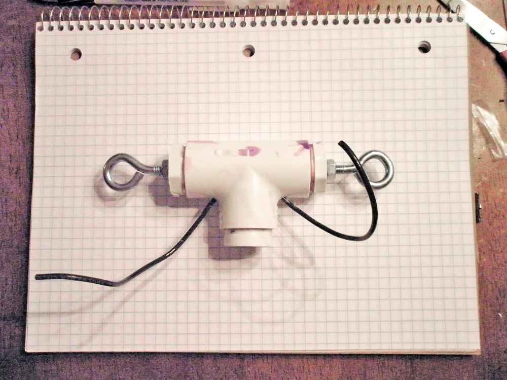
The "Tee" - Super-Tough Center Connector for Dipole Antenna
Shown below is just my example of how to build a very durable center connector for an HF dipole antenna. Though commercially available versions are cheap and easy, why not make one out of your scrap junk and do it differently every time you put up an antenna?
This one happened to fit my requirements; it was compact, waterproof and could hold the weight of a man or overfed squirrel! (sure, why not) The construction difficulty is a bit on the advanced side as it requires some metal grinding and cutting but the parts required are just several small 1" sized PVC pipe fitting parts, and no length-pipe was used as the connectors are more rigid and made of a stronger PVC. This will hold more weight than the connector end of the feed line could hold. I know, because I've had many of large tree limb bring down a good dipole. No guarantees though and the builder assumes all responsibility.
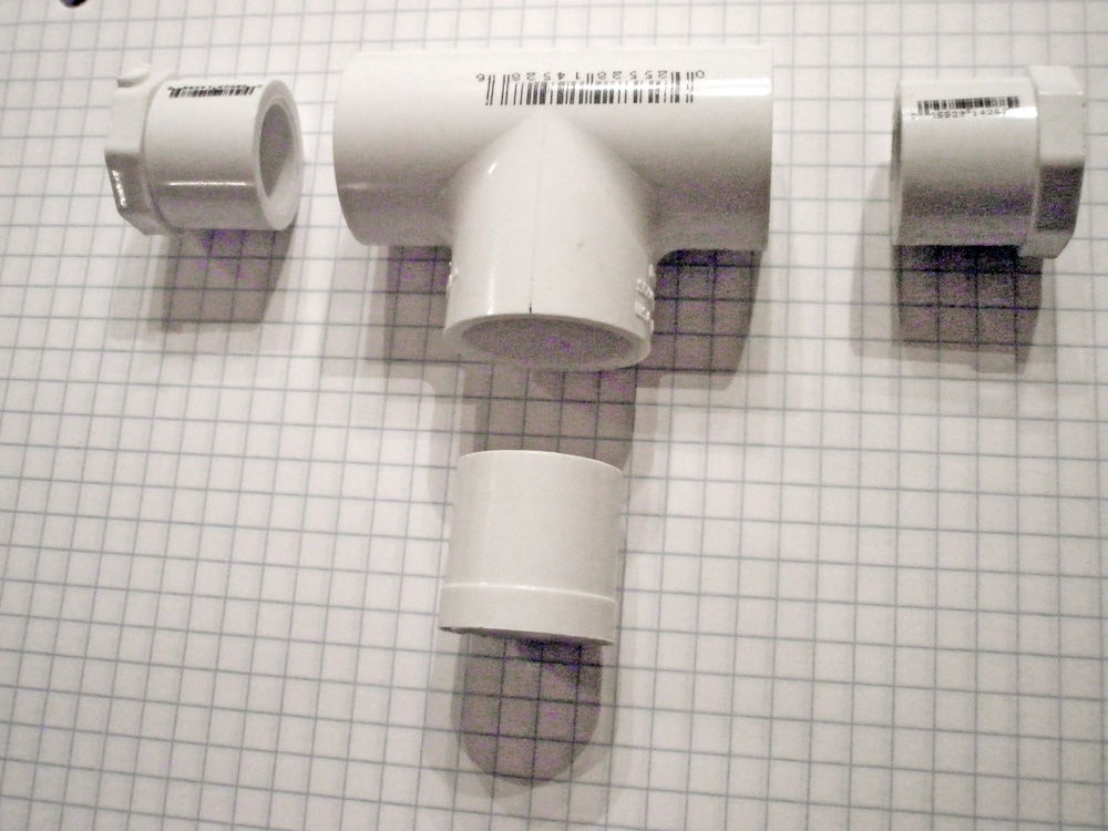
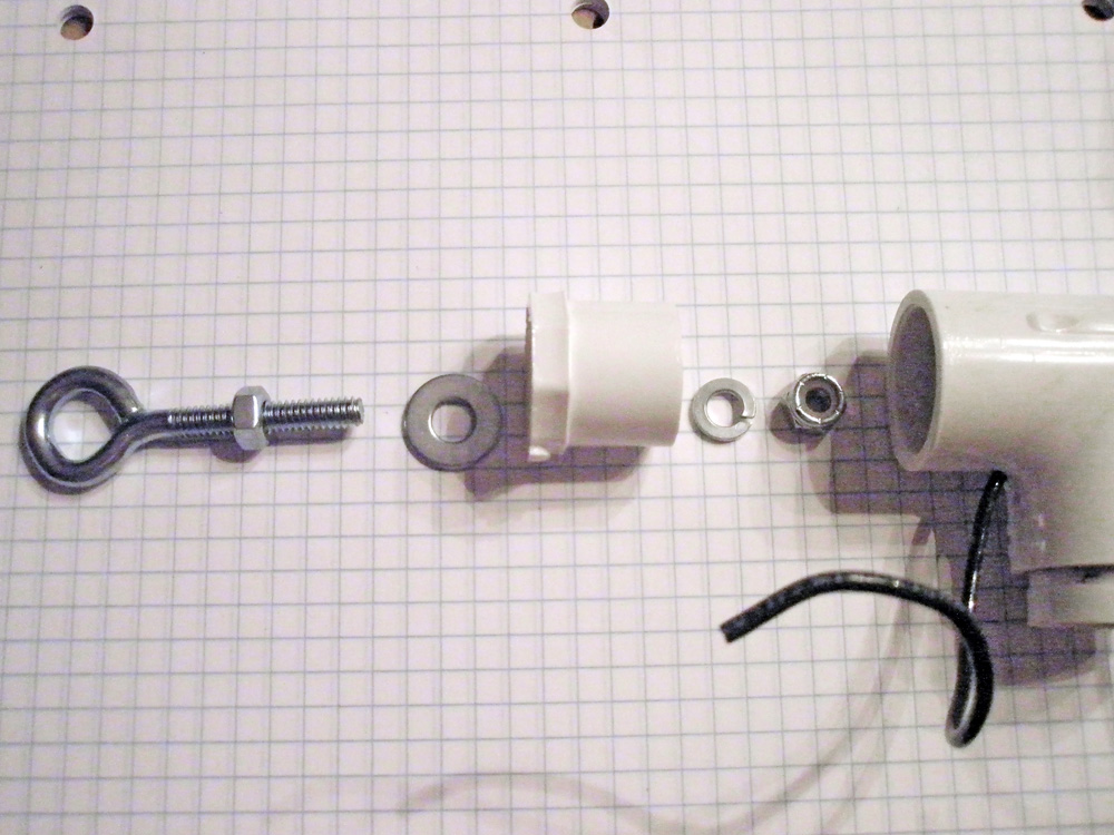
PVC pipe connectors
were used. No length-pipe was included. All 1" sized.
(Click
to enlarge photos)
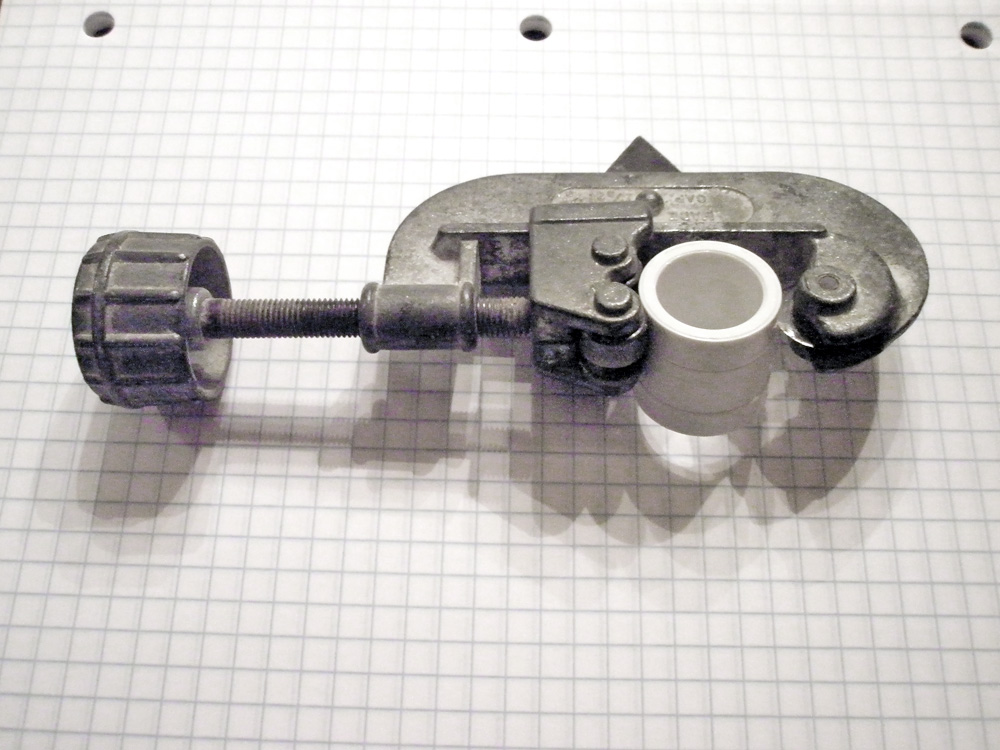
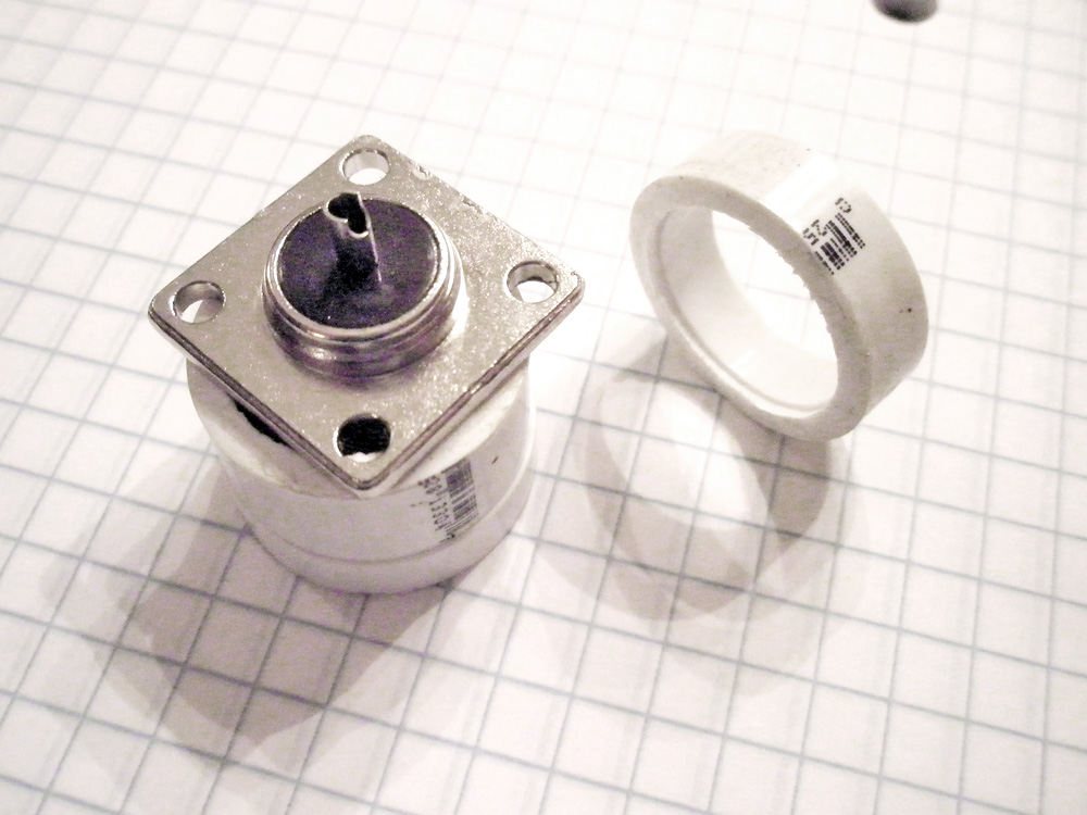
The Reducer adapter was cut in two, about a 1/4" down from the small end.
The Panel Mount
SO-239 UHF Connector to be sandwiched between the two halfs.
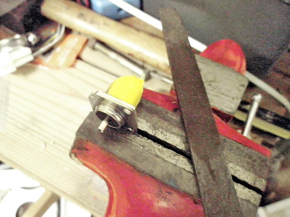
Problem: Square peg in a round hole... what to do.
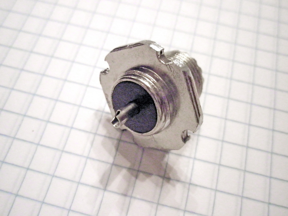
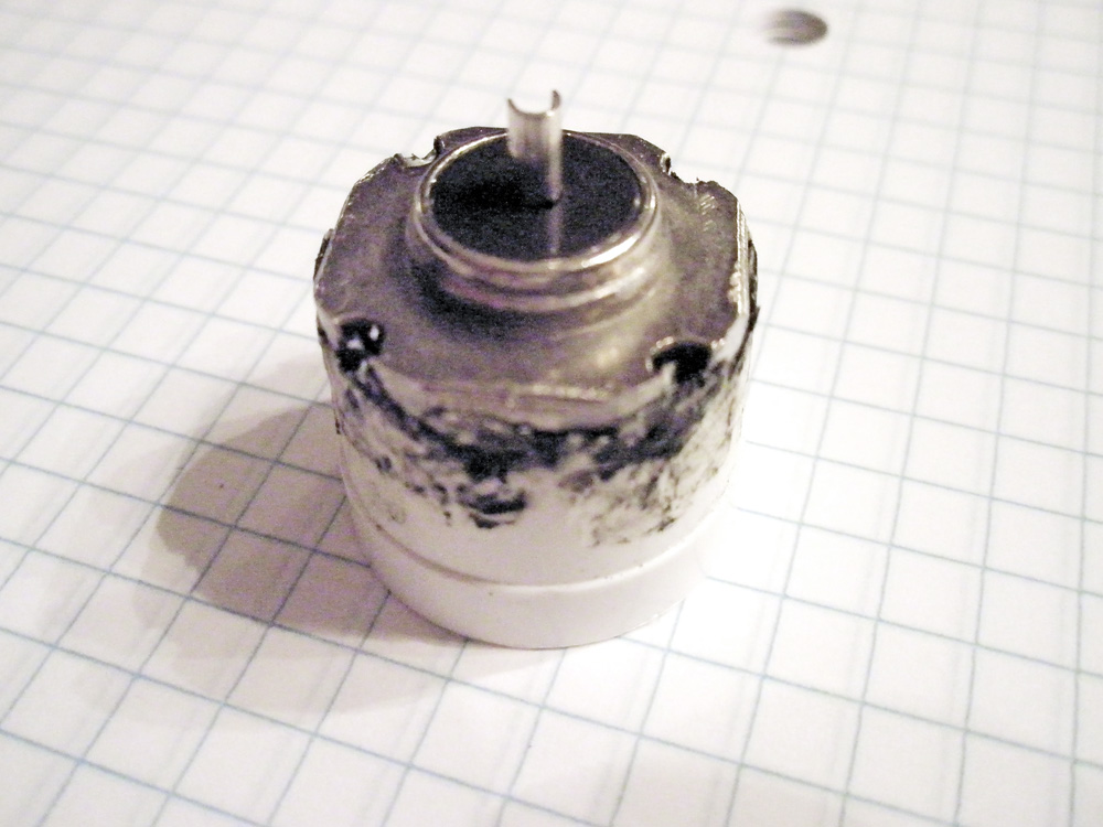
File the corners off
of the SO-239 until the base is round at the same diameter as the
Reducer.
Putting tape around the theads will prevent ruining the connector.
Readied...
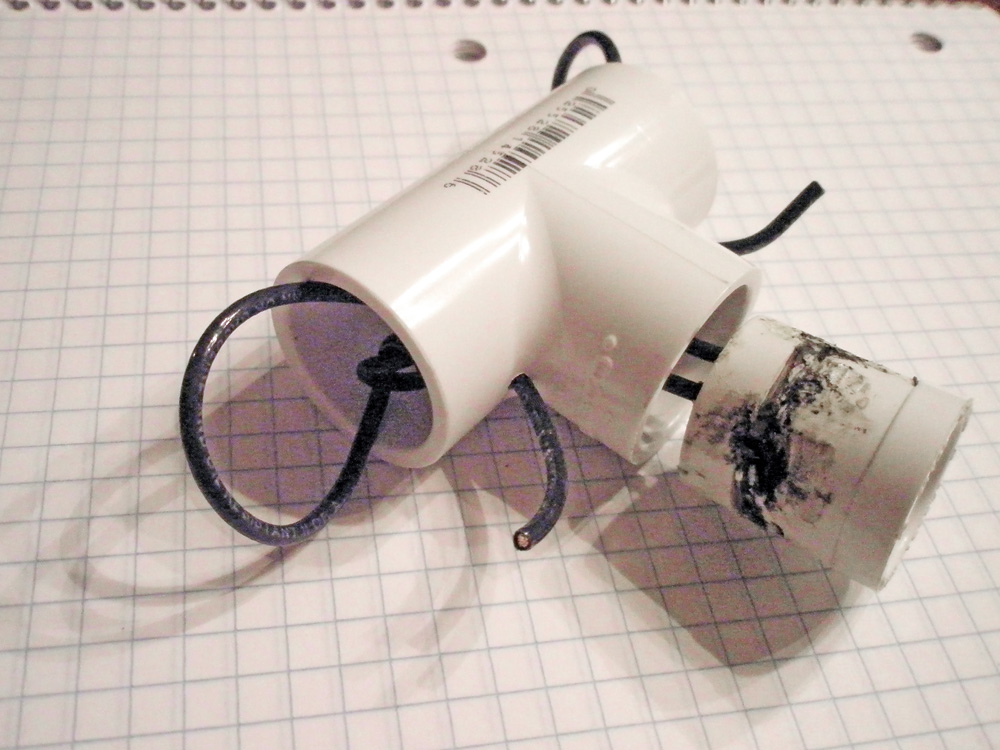
Ooops... I tried to
attach the SO-239 to Reducer by melting it with a soldering iron. Man,
that looks bad...
I recomend epoxy.
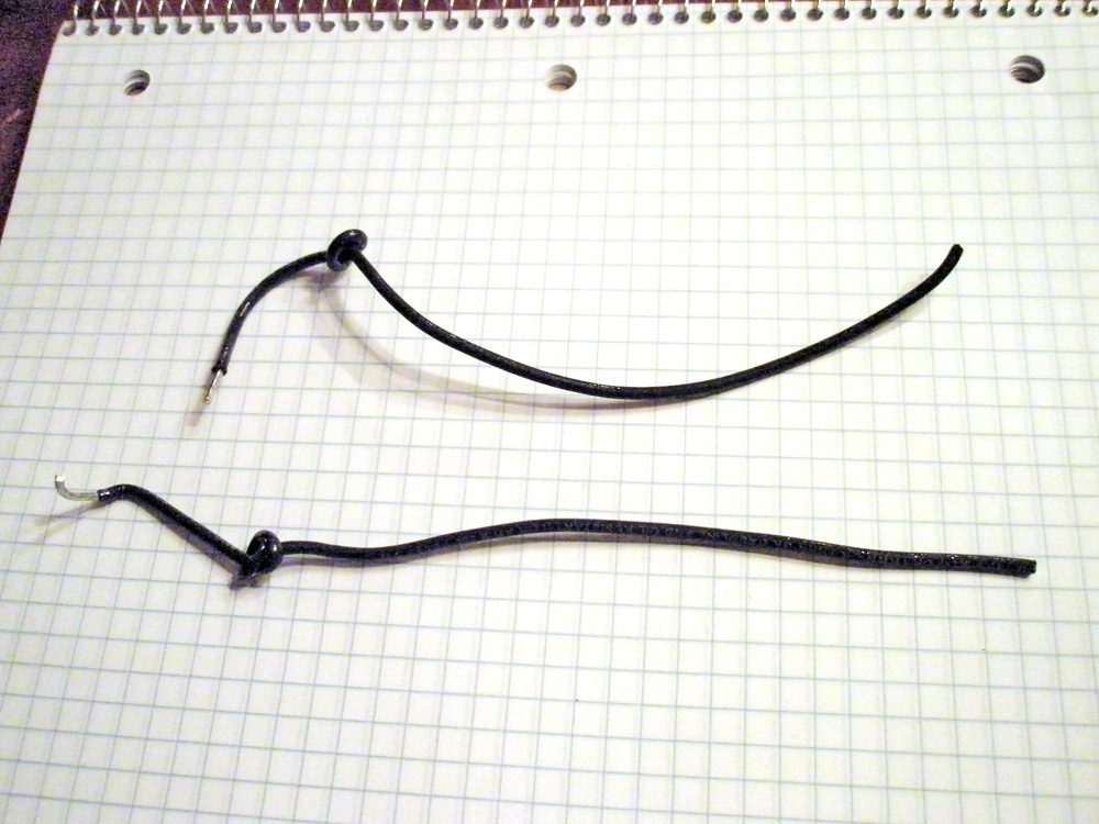
Leads are fashioned out of stranded #10 guage insulated wire.
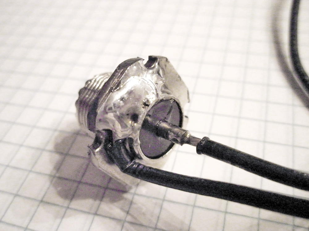
Soldered leads to connector. Keep outter lead close to round inslulator lip.
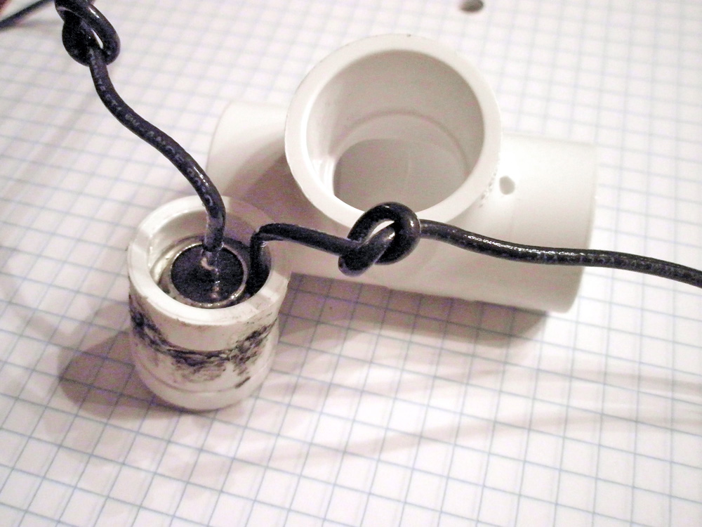
The prepped SO-239 with leads and two parts of Reducter glue (or melted) together.
Leads and connector ends are threaded in after access holes were drilled into T-piece
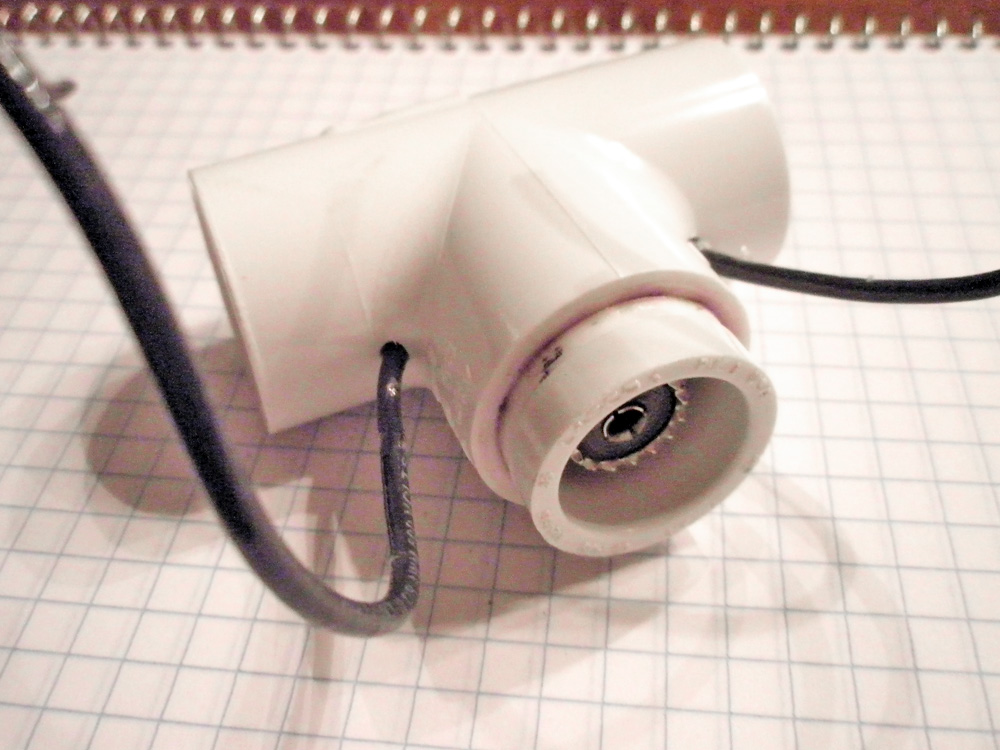
Connector glued with PVC cement into T-piece. Sealant placed inside lead holes.
End Caps drilled through to accept stainless-steel hardware.
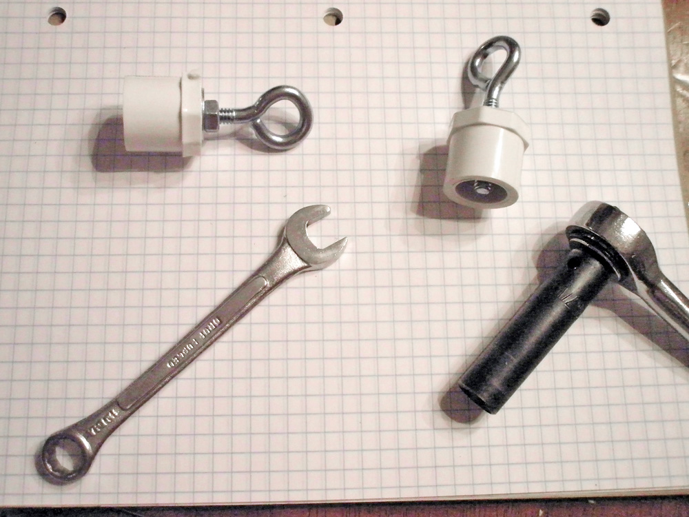
These are tough! Ratcheted together and ready to hold a massive dipole antenna!
Ends are PVC cemented together while being aligned. Test initially to prevent hardware touching lead connections or binding leads.
Final assembly,
ready to be soldered and attached to dipole wires.
Dipole can be pre-soldered directly to SO-239 for extreme
weather-proofing.
Edited:
06/26/20
(c)2020 Copyright - Michael A. Maynard, a.k.a. K4ICY
