I'm
going to attempt to build my first home brew, fully operating radio... that is, for ham
use.
It'll be based off of the popular PIXIE 2, which is a small kit available from HSC. Visit halted.com to order one for
yourself.
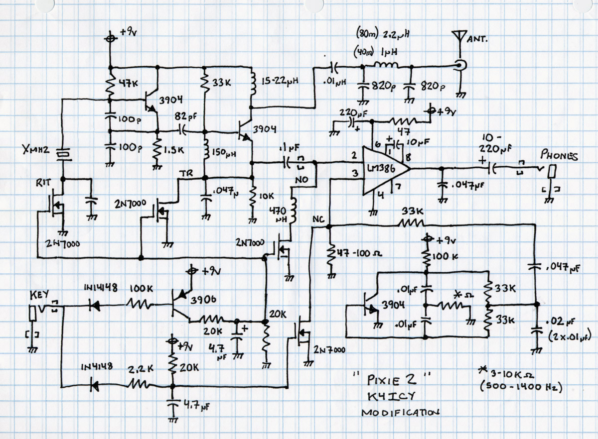
This is the second rough sketch schematic of my Pixie 2
with mods. The transceiver portion is in the top left. Below are the circuits for Side
Tone generation and switching array using mosfets..
[Pics will be added as I progress throught the project]
• Received the Pixie 2 kit from HSC - took five days to get it.
The kit was only $9, but you have to buy a crystal to use in it. I added a 7040 khz
crystal for $2.75. They charged a fee of $5 for not having $20 worth of goods on the
ticket. Shipping UPS was another $9.
I should have added the 80m crystal. But lesson learned...
My intent is to make a small QRPp rig set for 40m and stuffed into an Altoids mint tin. A
40m longwire is easy to take with you on vacations or hiking trips.
Later I'll move up to more pre-fab kits, like the RockMite.
• Did an inventory of what the sent me; A crystal, printed circuit board, axial lead
inductors, caps, resistors, transistors, an LM386 amp, etc...
• I set the kit up as shown in the schematic (transmitter portion only) on my
prototype bread-board. Wired the antenna to my multi-band dipole, set up my Yaesu 857-D to
receiver (without antenna) around the crystal's frequency.
• A nice carrier is heard which means the oscillator and PA work. I zeroed the 857-D
to find that the crystal is cut to 7039.4 khz.
But, since my MFJ-993B tuner is digital and the analog meter is CPU controlled. I
can't get a reading unless it's 2 watts or more.
I'm going to have to find a watt meter that can.
• I set up the audio portion of the circuit that contains the LM386... oh boy...
- Yes, I can get in 40m CW Morse code. Very faint, but audible. S1 or S2.
Although I copied K4ZNC booming in at an S9+! (He lives a half mile away...)
- Broadcast interference is through the roof! S9+20db over! A local FM
country station who's tower is only 2/3 mile away. A local AM station. WYFR shortwave from
Okachobee, FL.
- There is an annoying pop/click when keying down.
• Now the improvement design phase:
- Using a part of my code practice oscillator, I'll use a couple of 2N7000
MOSFETs to switch between the receiver and a Twin-T oscillator based side tone. The
switching is done gradually by the order of 100ms to create an envelope for the wave train
of both the transmitter and side-tone oscillator.
- I need ferrite beads! On the audio to the phones, to the LM386, the
keying line and anywhere else that can cause problems.
- A more robust filter for the antenna line. Basically a high-Q multi-pole
band pass filter for 40m.
- RIT! I want to try using the 2N7000s to switch a veri-cap in and out. And
I'd like to see how far I can bend the crystal.
Once I can reduce the BCI, I'd like to first try a 40m VFO circuit. Perhaps narrowed down
to a small section of the 40m CW band so that drifting is not an issue.
Next would be a 1 watt amplifier and switching mechanism to complete the project. Also, a
small long-wire tuner is not an impossibility.
At the moment, the circuit has the most aweful BCI and bandwidth issues. But I hope to
iron those out without making the rig too large to fit in a mint tin.
Updated 10/10/10.
• I found a bag of three lead ceramic caps that I picked up some 25+ years ago. They
had very small ferrite caps on two of the leads. YEAH!
I put one on lead to the power, the headphones, the cap in line with the audio to the
LM386, and the keying lead.
- Virtually all of the local BCI has been eliminated. Just the noise of power
line noise. International shortwave broadcasts can still boom in, but that is to be
expected.
The reception is also less robust and often barely
audible. Some extra amplification could be in order.
It is noted that adding the ferrite beads have introduced some
interesting inductances that change thoughout the breadboard.
Everything of course will be kept close and shielded in the final
install.
- Now I will concentrate on further tweaking the LM386. The audio is weak,
but I need to concern myself with the switching mechanism and click/pop reduction.
- It seems that the last two nights has had the nearby frequencies filled
with a contest or DX of some type.
Updated 10/12/10
• I pieced together the "Twin-T" based side tone oscillator so that an
audible sound could be produced when the key is down. It uses one NPN transistor and an
associated array of caps and resistors. I supplied the output through a blocking cap to
the other input of the amp. What I ended up with was a self oscillation in the amp.
But I found that supplying the side tone to pin-7 (bypass) of the LM386 allowed for audio
to be heard as desired. When the receiver audio is shunted to ground the volume of the
side tone goes up. However, using pin 7 seems to have helped with the BCI also.
- Now that I have acceptable audio signals from the receiver and side tone, I
can build a switching circuit to choose between the signals depending on the key state.
- I would like to smooth the transistion by 100ms to attempt ellimination of
clicks and pops, reduce splatter on the transmitted output and making the signals more
pleasant to listen to.
- Then to add RIT to the oscillator.
Updated 10/14/10
• Built the switching circuit and ran into all kinds of oscillations. The LM386 is
extremely sensitive to even source voltage fluctuations.
I moved the side tone signal line to pin 3 (from side tone) of the amp. I
also placed a choke coil in line with the switching circuit that grounds audio on pin 2
(from receiver).
The circuit now operates roughly as intended. Contacting the keying lead of the
switching circuit causes the LM386 to go from amplifying the receiver output to the side
tone.
- The volume/gain of the side to is too large. The LM386 has the
"bootstrap" capacitor affixed that causes it's gain to be 200db. The side tone
oscillator doesn't need it.
I've tried to run the side tone through a resistor network, but the
gain is still too high. Dumping more of the signal to ground seemed to increase the gain.
- There is too much capacitor storage or lag that is causing a delay in the
return of the receiver signal, along with a slight wine as the signal is bled in.
- A large pop/click is still prevalent.
Updated 10/19/10
- Components were adjusted and the switching works well. The side tone
oscillator is too "hot" for the LM386 which has been set up for 200x gain.
Either there is a way to quell the volume of the oscilator by which
resistor networks are not working - or - I may have to take the gain cap off of the amp
chip and pre-amp the receiver signal with a 741 op amp.
Updated 10/20/10
• I applied the output of the side tone oscillator to pin
3 of the LM386, through a DC blocking capacitor and 2meg ohm resistor. The volume is
perfect.
• The shunted muting control from the switching mostfet was taken from the
oscillator circuit itself and applied after the blocking cap before the resistor.
Consequentially, when placed after the resistors before the input of
the amp, muting was not 100%.
• Installed a 2N7000 mosfet from the normally-open switching control to pull
the final PA oscillator to ground to initiate transmit mode.
- The "chunk" or popping when keying is still prevalent. There is a
lot of current pull to the different stages in this instance.
One possible solution would be to apply a small pulse to pin 7 of the
LM386 to mute the amp just long enough to silence the pop.
A mosfet could be used with a discharging cap.
- I now have full control over transmission keying and T/R switching.
- The next step is to experiment with adding RIT to the crystal oscillator.
Using a mosfet to bypass a capacitor and "bending" the crystal.
This will have to be done with an instaneous state mosfet
circuit as the progressive change switching used to make the audio sound better will cause
an unstable signal to be put on the air.
- Since I dissabled the 200x gain on the LM386 I need to run a pre-amp on the
receiver signal.
I'll attempt to use a 741 op amp in a narrow band pass
active filter configuration with at least 10db gain. Killing two birds with one stone. It
will help to eliminate a lot of interference and thin the CW signal herd.
- Next, I'd still like to develope some type of VFO.
Updated 10/25/10
• Set up a 741 op amp. The result was not satisfactory. The peak frequency
response is impossible to aim unless you are using a couple of potentiometers. And the
gain was not enough to work with.
- I'm taking that out and thinking about using another LM386. I would rather
had found a way to bring the volume of the side tone oscillator down, but this is an
impedance issue and I want to keep the parts count simple and not implement any
transformers.
- At least with the LM386, you can control the gain. I'll just have to
content with the BCI and other interference.
Updated 10/27/10
• Using an LM386 was unsuccessful as well. LM386 amplifiers
tend to be prone to spurious oscillations.
• Taking a step back and implementing the sceme used by other Pixie 2
designers, I ran the side tone through pin 7 of the LM386. A 33k resistor is used to limit
the volume.
• The emitter of the side tone oscillator NPN transistor is now inhibited by a
mosfet switch.
- The levels of receiver and side tone are now acceptable for headphone use.
There is a major issue left with popping static upon key contact.
- I'll attempt to calm the popping, maybe even a temporary muting of pin 7.
- I'll add switching to add capacitance to the crystal to shift the frequency
upon transmit to add RIT.
Updated 10/29/10
• I was getting too much interference and unwanted oscillations with this
configuration, so I put the side tone signal back to pin 3 of the LM386 through the 33k
ohm resistor, with a 100 ohm resistor to ground at pin 3 to control the volume. There is a
slight volume drop when the transmitter PA is operational.
- I'll try to see if the drain of the mosfet can be put back at pin 3. If
I can leave the side tone oscillator running I may be able to stop some of the
popping on key change.
Updated 11/04/10
• Re-instated the opposite state of the mosfet switching control and used it to drain
pin 3 (the side tone input) of the LM386. This allows the side tone oscillator to stay
running while the audio is chosen between it and the receiver.
An amount of popping between key states have been reduced. There is still a large amount
and I may not be able to remove it since the LM386 is in 200x gain mode and is surely
amplifying any current changes in the whole of the circuit.
- Since the switching and amp part of the circuit is stable enough for basic
use, I'll work with providing some basic RIT to the crystal.
- Next, work will envolve creating a VFO to allow for frequency agility.
Updated 11/09/10
• Installed the RIT (CW frequency offset). By adding capacitance to the series of the
crystal, you can "bend" the oscillation frequency. In line I placed a 70pF
ceramic cap in line and the frequency was risen a good 2 khz. I'm using a mosfet from my
switching circuit to bypass the cap to bring the crystal back to its fundamental
frequency. 70pF bends the frequency too far. So I added three 100pF caps in parallel
(300pF) through the mosfet line. The mosfet line now adds 300pF to the 70pF to yield
370pf. More capacitance will only bring the frequency down so close to the fundamental,
but within 1.5kHz. But two things happen. The active frequency is now 7041kHz instead of
7038kHz and the offset distance is now 750Hz on the nose.
- I'll use a separate mosfet circuit that is active when the key is up, so
that the receiver circuit sees a capacitance of 370pF bringing it to the lower frequency
to that the other stations CW signal lands at 750hz in my audio passband. When the key is
down, the mosfet will deactivate leaving the ciruit to only see 70pF and raising the
frequency 750hz higher to then transmit leaving my signal at 750hz of the other operator's
audio.
The mosfet circuit has to be switched on and off fast to avoid sweeping the transmitted
signal accross the band, which would make the received signal sound lousy.
- I'll put a 5v voltage regulator (in a TO-92 package) to keep the frequency
from shifting due to activity in the rest of the circuit.
- I'll then see if the slow switching mosfet switches allow the PA section to
"shape" the output CW signal. But if there are problems with "current
starvation" or other fluctuations this will not be possible, especially since key-up
causes the RIT to swing the crystal back too quicly before the PA is deactivated.
- Can this be done with a VFO as well?
Updated 11/10/10
Update: As of spring 2011 I've not been able to procede with this project. Since the last
update, I've taken the role of an ARES-AEC for my county. With that and among other things
going on: I've not found myself with much time and will power to continue in the near
future.
I've determined that this circuit needs a few enhancements before I can attempt to make a
prototype:
To get the optimal frequency separation between transmit and receiver requires that I
"bend the crystal" in the oscillator a good 750Hz.
I've discovered that the more the oscillator (or the crystal itself) is
"starved" for current, the more you can bend the resultant frequency.
Also, the problem of poor frquency accuracy became more prevalent as more parts of the
circuit were added.
To accomplish a working design for good T/R switching, I'll have to employ a stable power
supply and more switching control - especially one that can push the crystal to it's
limits.
SO! It appears that this humble 2-transistor CW rig is now being over-re-engineered!