The "ICE BOX"
My
Small Wonder Labs SW+40 QRP Transceiver Kit (and accessories)
 SOTA Tuner SOTA Tuner  New Terminals New Terminals  The SW+40 Kit The SW+40 Kit 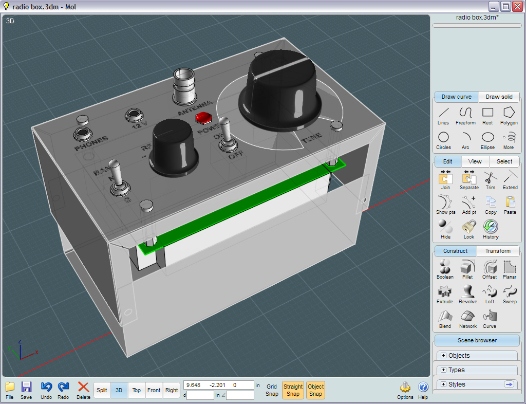 Moi3D Moi3D ") Enclosure Enclosure
 PicoKeyer+ PicoKeyer+  Batt Status Batt Status  More Moi3D More Moi3D  The Guts The Guts  Miniboots Amp Miniboots Amp  Elecraft T1 Elecraft T1  Quick
Antenna Kit Quick
Antenna Kit  Control
Labels Control
Labels
Use this Quick-Menu to see below
- for
the addition of the SOTA Tuner, Elecraft T1 Automatic QRP Tuner as well
as my home-brew "Miniboots" 1-12 watt QRP linear amplifier!
NOTICE:: The ME40+
now supersedes the SW+40
Rick Choy, N3HXT, at Midway
Electronics
in Middletown VA has taken on Dave Benson's SW+40 and is now again
available for sale, now called the ME40+! Rick has spiffed
up
the original manual to have a "Heathkit" style to it and offers the kit
in 40, 80 and 30 meter versions with 20 meter version on the way.
Visit http://www.midwayelectronics.us/qrp/index.html
or contact Rick at midway7726@gmail.com for more
details. You can order the MExx+ on eBay as well as Rick's
website.

[circa 2012]
Well... I finally
got to build that CW QRP rig I've wanted to try for a while!
What a Christmas present...
QRP is an old telegrapher's term for "low power", which is a past-time
within the amateur radio hobby.
Believe it or not, the weaker radio signals produced by these types of
radios routinely span the globe!
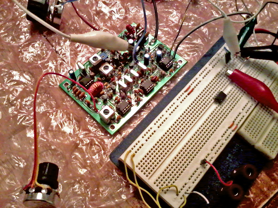
A
very compact station! The photo on the left was
what the
radio looked like January 2012 - The photo on the right shows the
(partially) completed
radio in April 2012.
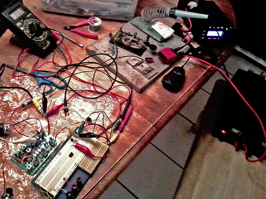
 Cool! A more recent
update to the nearly completed K4ICY Portable QRP Station. (March 2013)
Cool! A more recent
update to the nearly completed K4ICY Portable QRP Station. (March 2013)
The indicator
light on the Miniboots amplifier doubles as a reading light!
Last year I had
the chance to play around with the Pixie II kit. It was a fun kit to
tinker with, but as a direct-conversion single frequency radio with no
selectivity, it lacked many
important features that were needed in a rig that could be
realistically operated. Some folks enjoy them, but it wasn't for me.
Two such features in particular
was a true TX/RX offset, a side-tone and some good selectivity.
If your into
CW, kit building or QRP and have never heard of the SW+40 I suggest
looking at the reviews on eHam.
[Update
summer 2012-2013 - Dave Benson stated that he was retiring
and
halting all sales of kits including the famous "Rockmite"]
[Update - Small Wonders Labs has shut down permanently]
Dave
Benson, K1SWL has developed a build-it-yourself transceiver that is
very well developed, compact, and comes with a commercial-grade printed
circuit board.
At only $60 for the main kit, for it's very good
performance it's one of the best deals out there for those hams not
afraid to pick up a soldering iron.
An additional $19 you can get all the external controls, knobs and
sockets required to get the kit operational.
And it only took two weeks to get the kit in hand.
Specs:
• 10.5-14 Volt
operation
• Receiver
Type is Super Heterodyne using a crystal network for filtering
• Output
Power has been set to 2 Watts on a 50 ohm antenna load [March
2013 - Output set to 0.7 watts to drive the Miniboots 1-12 watt
amplifier]
•
Frequency Range: Four
sub-bands set within the entire
40 meter (7 mHz) CW Band
Band A • 7000-7034 kHz
Band B • 7032-7066 kHz
Band C • 7061-7096 kHz
Band D • 7091-7126 kHz
Side-Tone and audio bandpass is set at 800 Hz.
Built-in PicoKeyer-Plus Firmware V4.0 ::: 4 text memories, dual speed
(5-60 wpm)
"Iambic" Keyer for use with dual paddles, Straight-Key operation
automatic.
See the
schematic diagram here:
See the
instruction manual (SW+40):
See the Elmer
101 Study Course:
To start off, I ordered
a miniature QRP tuner as to match my future SW+40 to its antenna.
Rumor has it that the final transistor in the SW+40 is not only
sensitive and prone to blowing - but is obsolete and extremely rare to
obtain.
The
SOTA QRP Tuner
Purchased as a kit from QRPKits.com
(eHam
review)
This
is a tuning device required to electronically match the antenna to the
SW+40, by essentially "tuning" the inductive and capacitive reactance
of the antenna circuit.
This is a mysterious subject to many new
radio enthusiasts, but more information can be had through the learning
material of the ARRL.
While the SW+40 kit from Small Wonder Labs
was impeccably packaged and well organized - I have to state that the
SOTA Tuner from QRPKits (AS WELL AS OTHER KITS) was a different story.
Number one, the
parts for the SOTA Tuner were incomplete, a
.01 uf capacitor was omitted and I was given double order of the 51 ohm
resistor set.
Number
two, the circuit board, when placed in the metal housing provided - did
NOT fit!
I had to find a suitable quality capacitor of my own and
I had to file a 1/4" square out of the corner of the board so that it
would fit.
With that, though, the SOTA Tuner actually works! And
works well. It's really a simple solution that has proven itself
amongst many hams operating on remote mountain cliffs.
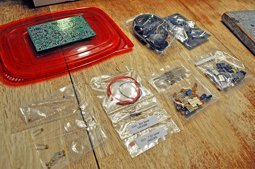
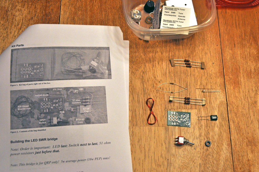 These are the parts provided by
the seller (Incorrectly) These are the parts provided by
the seller (Incorrectly)
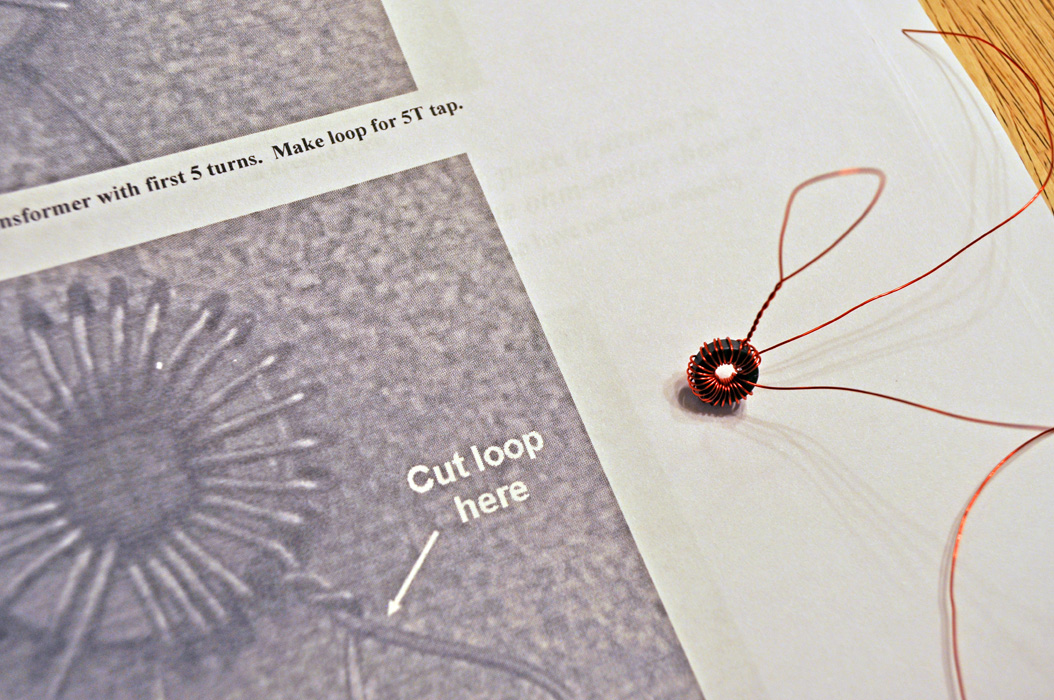 This is the first toroid I've
ever wound - not so tough. This is the first toroid I've
ever wound - not so tough.
The
Toroid, which is kind of closed transformer or an electro-magnet coil
of wire around a
ferrite doughnut that acts as an inductive element to the
circuit it operates in.
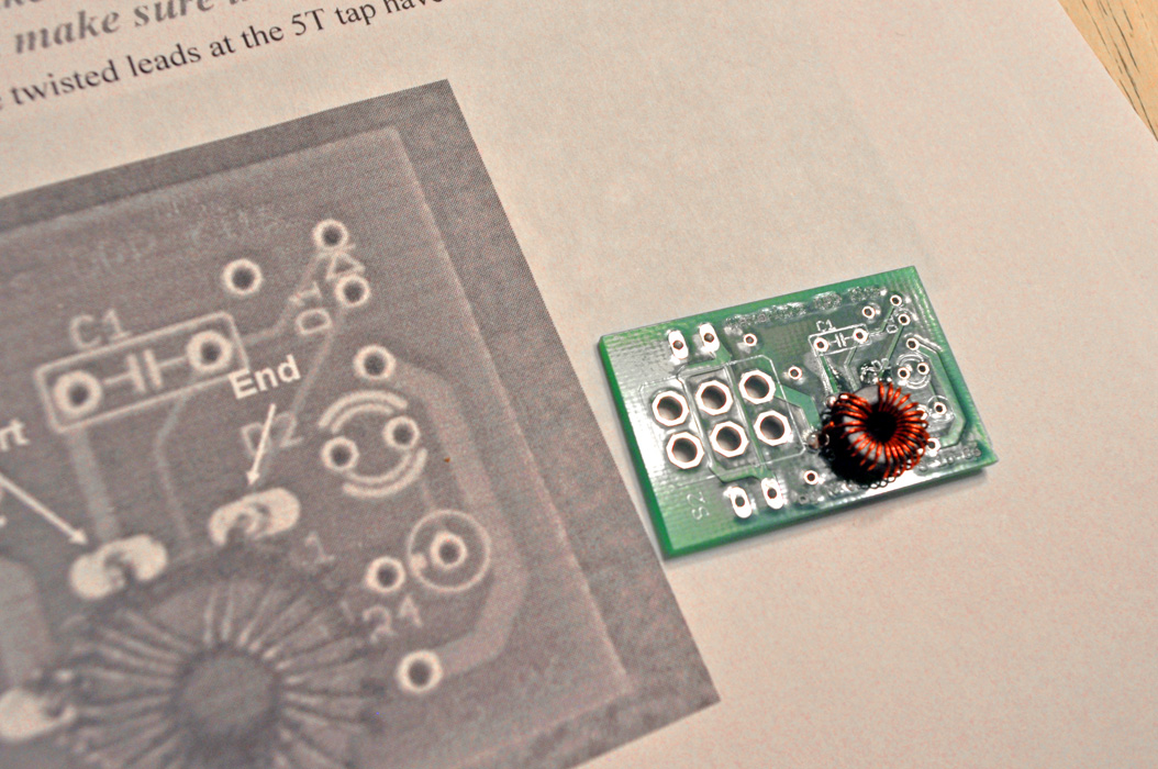 Here it is
soldered to the printed circuit board ("PCB")
Here it is
soldered to the printed circuit board ("PCB")
 After a
little work, the handful of components are soldered to the board.
After a
little work, the handful of components are soldered to the board.
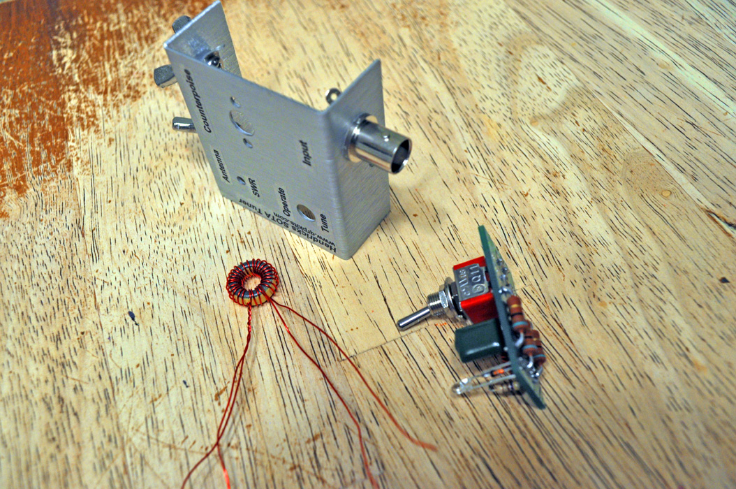
By this point, I have applied the airplane model stickers to the metal
case and attached it's outboard connectors.
There is a second toroid also shown above.
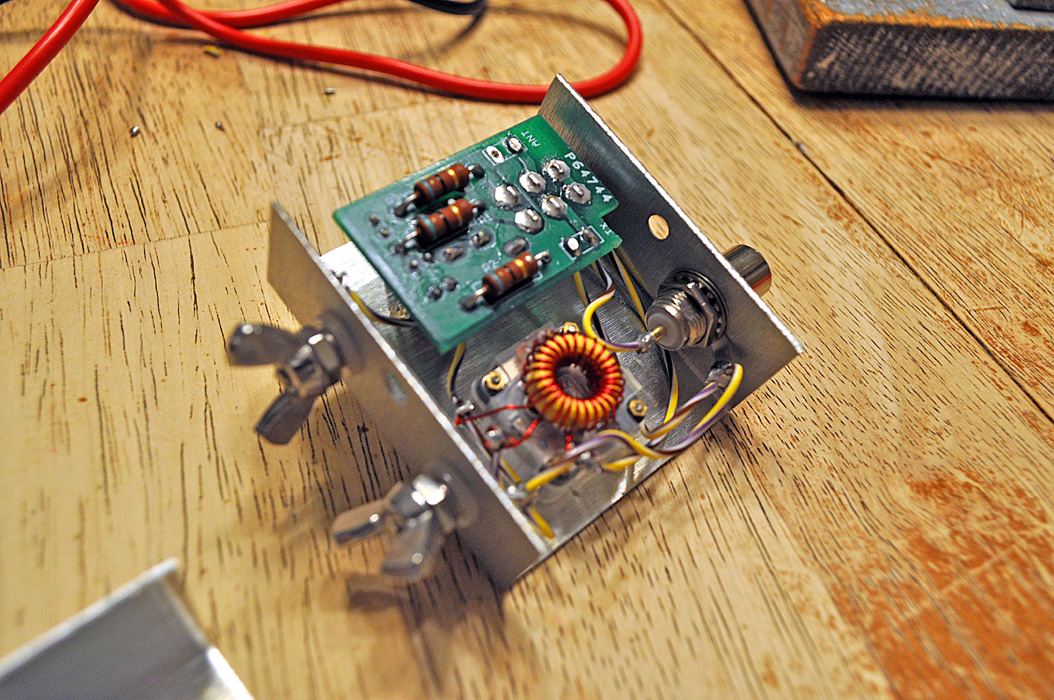 Here are the main components
installed and wired to form a circuit. Here are the main components
installed and wired to form a circuit.
Notice the chunk I had to file out so that the bolt holding the case
halves and it's fastener would fit.
Here is the completed SOTA Tuner
kit.
This box will have to be operated in conjunction with the
SW+40 for every use.
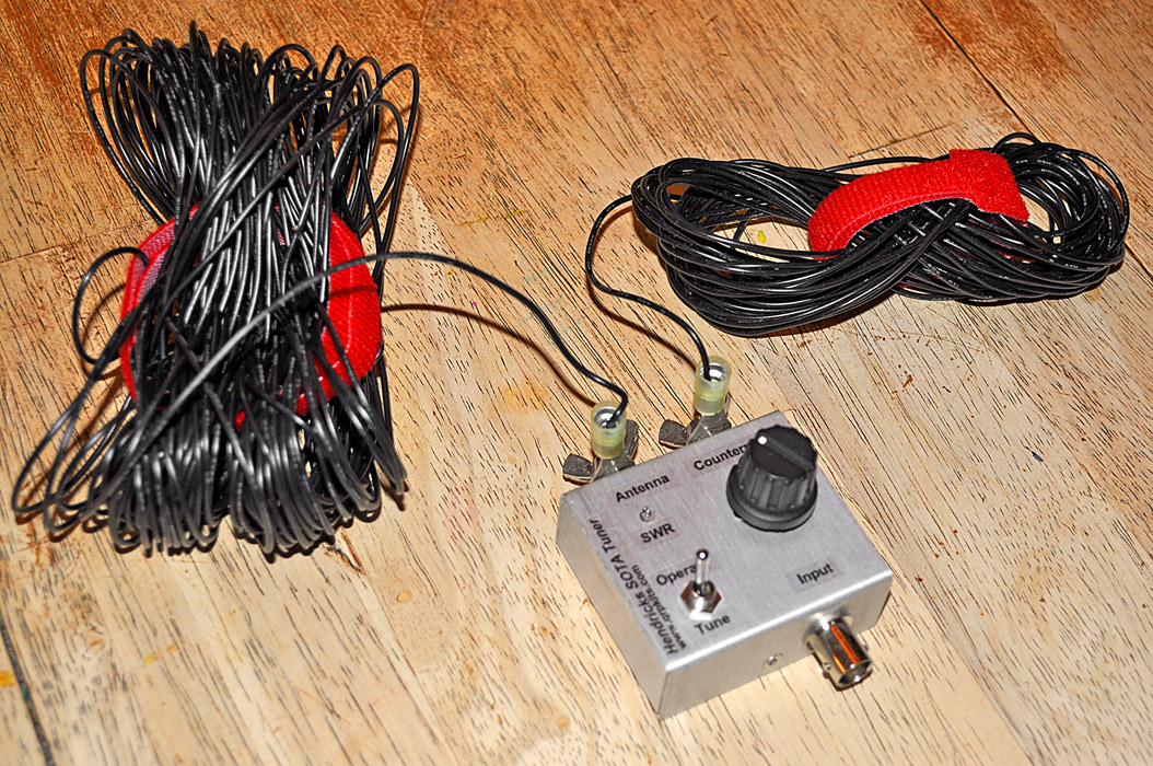 The attached wire
is the antenna system for the transceiver.
The attached wire
is the antenna system for the transceiver.
The antenna wire is "US Navy"-style wound for rapid and easy
deployment. The "Antenna"
side is a 63' wire that is strung to any tree limb. The other side is
the "Counterpoise" that serves as the electrical ground for the
antenna, required for the radio energy to have something to "push"
against when transmitting.
Update: [01/11/14]
Upgrade for SOTA Tuner Terminals
Frankly, the thumb-screw
(wing-nut) arrangement designed for antenna connections to the SOTA
Tuner outright sucks!
They were prone to coming loose, even during transmit and even after I
tried lock-washers on the eye-lugs side, and on top of that, as I use
one set of wire for different tuners (see the Elecraft "T1" below)
unscrewing the thumb-screws were a pain.
For the life of me, why
in the heck didn't Hendricks
QRP Kits not spend the extra two bucks to use banana-type
terminals... I mean, c'mon man!
Well, problem solved,
and I suggest anyone
building the SOTA Tuner, which by the way, actually works great, should
consider
installing the better terminals in place of the wing-nuts!
 Shown here is SOTA
Tuner and a new pack of "Banana Jack Insulated Binding Posts" RS#
274-0661
Shown here is SOTA
Tuner and a new pack of "Banana Jack Insulated Binding Posts" RS#
274-0661
Radio Shack sells these
great
banana-terminal posts for a couple of bucks which seat in with a small
bolt and is able to not onle accept "banana" spring plugs, but can
screw-tighten spade terminals. An additional hole is
available to
hold bare wire ends.
The SOTA Tuner uses a
pair of nylon
insulator washers to separate the terminal bolts from the chassis, so
I'll re-use those, and you should be able to also use the terminal tabs
soldered to the circuit. The only more complex task you have
to
do here is removal of most of the parts in the tuner to access the
terminal bolts.
 Here is the
disassembled hardware.
Here is the
disassembled hardware.
After the tuner's
components were un-affixed
and moved aside, the original wing-nut assembly was taken out, go ahead
and leave the nylon washers in place.
 New terminal held
in place as hardware is installed
New terminal held
in place as hardware is installed
I temporarily removed
the cap from the new
banana terminal and a very small screwdriver (or nail) is great for
holding it in place as you attach the original circuit connection
terminal lugs to the back. I used the pre-existing insulator
but
added the provided paper washers.
Detail of the installed banana terminals
Here you can see that I
used the original
terminal lugs but added the new ones along with the originals as they
had a smaller hole that
matched the new smaller terminal bolt's diameter. I also used
the original
lock-washers as well as the second nut - that way, the new terminals
will be less likely to come loose. It's a good idea
to test
the antenna-side terminal for accidental continuity to the
chassis. It's not necessary for the "counterpoise" side to be
isolated as it is already grounded, but it looks nicer to have the
terminals sit at the same height.
 New
Banana-Terminals Installed
New
Banana-Terminals Installed
The new terminals are
ready for QRP
service! Not only can the antenna line and counterpoise be
connected in a pinch, but allow for an emergency disconnect if the wire
is say - unexpectedly pulled away by a wind-driven tree-branch, or
worse, an
unaware passerby! Yes, both have happened more than a few
times
with the SOTA Tuner ending up on the ground. (and diningroom floor)
The Small Wonder Labs
SW+40 QRP CW
Transceiver Kit
 Here is the
arrangement for the packaged parts as provided from Small Wonder Labs.
Here is the
arrangement for the packaged parts as provided from Small Wonder Labs.
I
was not used to building large kits, this one has a lot of parts - but
Dave Benson did a wonderful job organizing and packing these many
components into logical groups.
 The component soldering and
installation process took ten hours! The component soldering and
installation process took ten hours!
There
were hundreds of contact points that had to be soldered. Each were
trimmed and inspected. The kit included five toroids that
had to be
wound by hand!
The multi-VOM meter was used to check for continuity throughout
appropriate parts of the circuit board.
The instruction manual was thorough and easy to work through.
I
spent several days at my leisure to build this kit and was as
meticulous
as possible. I chose to follow through the instruction manual for the
construction process.
Many have used the step-by-step course study online
from Elmer101, going through each stage, making measurements and
learning the intricacies of this radio plus it's theory of operation.
The link to this very informative course is: http://www.qsl.net/kf4trd/lessons.htm
I
suggest reading through this before building your own. If you are going
to truly experience the fun of operating a QRP rig that you built
yourself, you should understand some of it's basic operation.
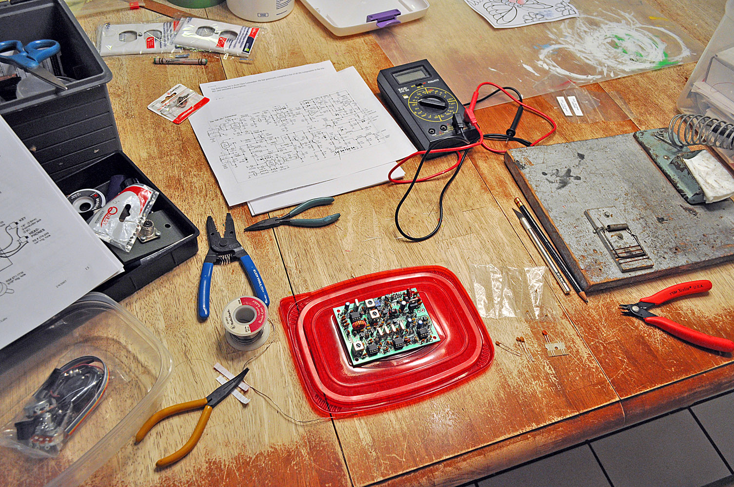
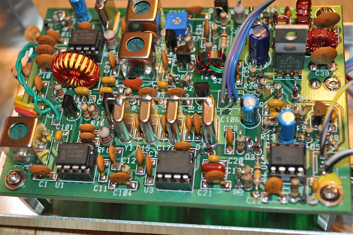
 The
completed circuit board was checked and re-checked.
The
completed circuit board was checked and re-checked.
The
next phase was to connect the control potentiometers (variable
resistors) and run through the manual's procedures on fine-tuning and
aligning the internal circuitry.
The radio will be dead for all intents and purposes, unless the handful
of control parts are tuned properly.
 At this
stage, power level was adjusted and filters were aligned.
At this
stage, power level was adjusted and filters were aligned.
There
are two ways to read the transmitter output wattage for final
adjustment. I used a combination of both: First, the instruction manual
describes and easy to build circuit that allows your volt meter to
provide a reading that corresponds to the output wattage. The signal is
converted into a usable voltage for the meter. A basic math formula is
used to convert the voltage reading to watts - and visa-versa.
[Update!]
See Tweak below done on 01/2013... The instructions for Dave's RF
voltmeter circuit were somehow off! The output was set too
high
and caused problems.
For
a
concise method of measuring RF voltage without a real wattmetter -
please see my Weekend Radio article in The Printed Circuit - Newsletter
of the Tallahassee Amateur Radio Society for April 2014 - Page
14 [Click Here for Article]
The second method involves using an actual HF wattage/power meter to
test the output.
My MFJ-993B will not auto-tune anything under 3 watts input but will
give me
a digital reading down to the tenths of a watt.
The
operation frequency range was determined here too. The SW+40 allows you
to choose operation in any portion of the 40 meter amateur CW band.
The
stock range of tuning for the VFO (Variable Frequency Oscillator) is a
decent 35 kHz, but this value can be changed as stated in the
instructions to not only make the band as narrow or
wide as the builder desires, but also determine the band's frequency.
A note of caution here: widening the band range will sacrifice
selectivity, but you can bank smaller widths to get more range without
sacrificing quality...
I first chose to make this a two-band radio by placing two separate
sets of capacitor banks on a SPDT selection switch.
Later,
I added a four-position rotary switch and added two more bands to widen
the tuning range of this rig to encompass the entire 40m CW band!
NOTE: A standard 10-position rotary switch from Radio Shack, by
removing or inverting the position of its stop tab can easily be
converted to either a 4 or 12-position switch!
Ceramic
disc capacitors called "NP0"'s were used to help prevent temperature
affected frequency drift. These are orange, round and flat with a black
dot painted on top.
They can be found at Mouser.com,
and I happened to find a large surplus pack at
Radio Shack.
 This is the
final circuit board which has been mounted in a stock Radio Shack metal
enclosure.
This is the
final circuit board which has been mounted in a stock Radio Shack metal
enclosure.
This metal
box was only $3, and was the absolute perfect size.
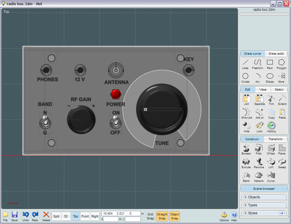
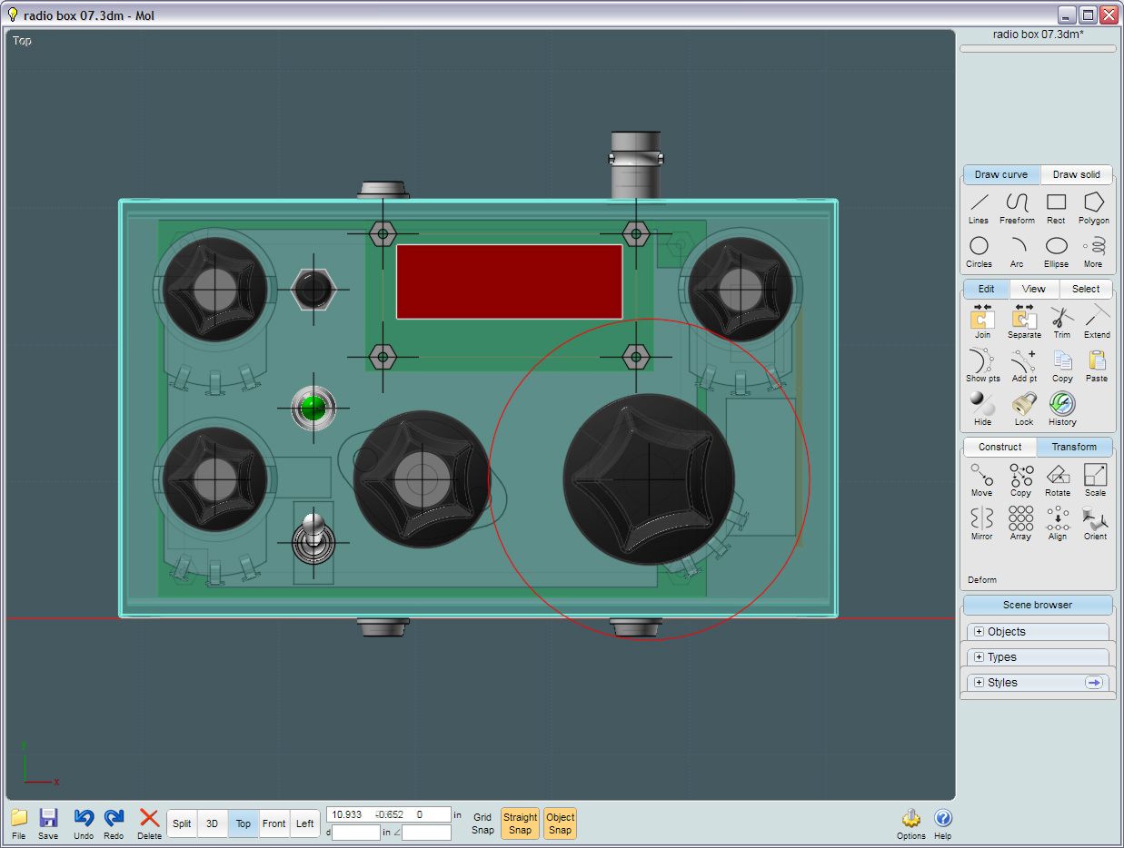
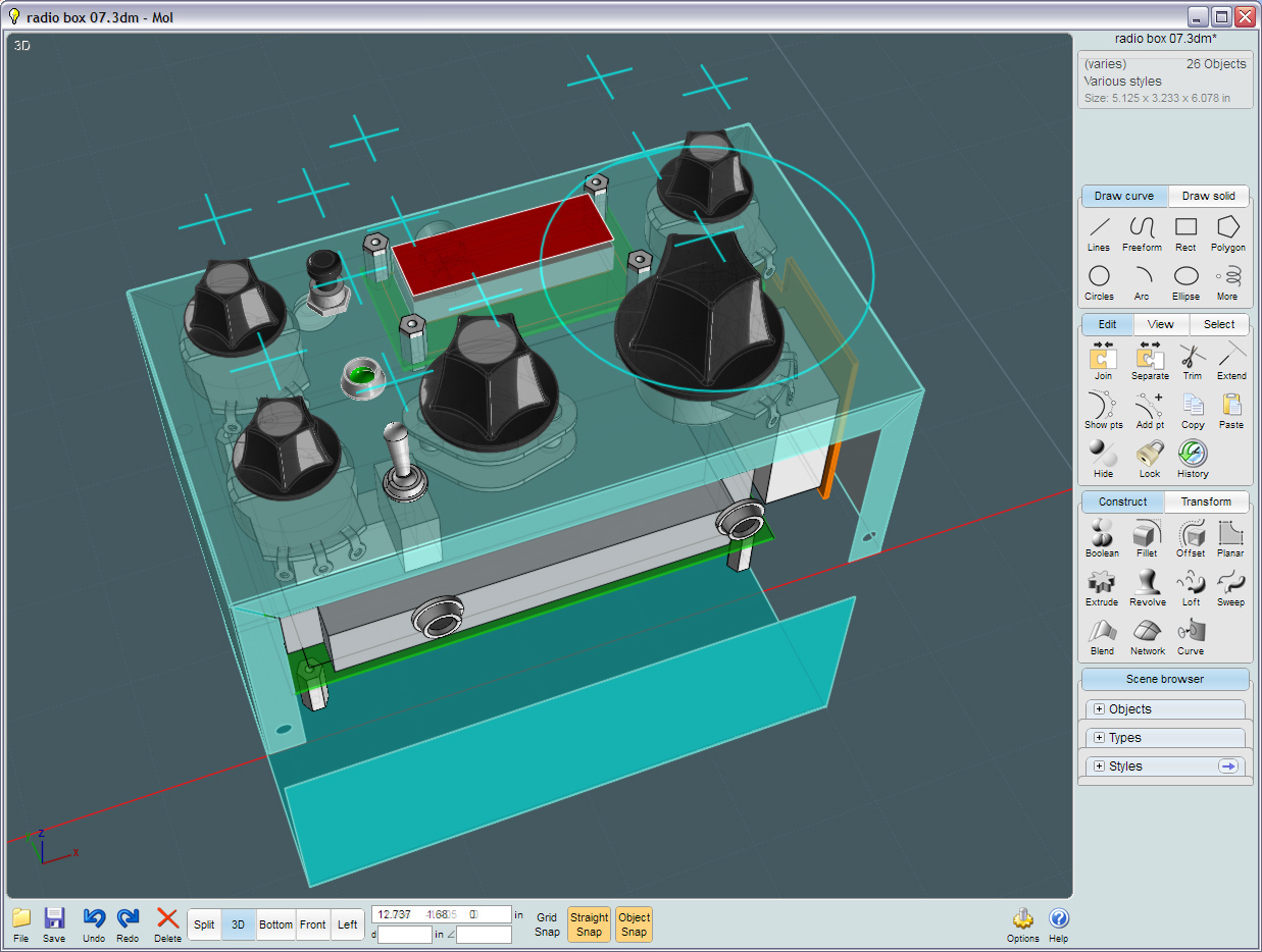
Moi
(Moment of Inspiration) Visualization
- Using a CAD program to accurately engineer a homebrew project...
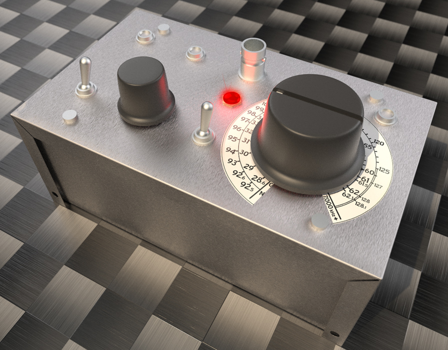 This picture is not a real
photo, but was first designed virtually in
the CAR program: Moment of Inspiration. This picture is not a real
photo, but was first designed virtually in
the CAR program: Moment of Inspiration.
Visit Moi3D
at http://moi3d.com/
Moi3D is
a NURBS/spline-based 3D design and CAD program created
by Michael Gibson, a
one-man
team.
The application is very powerful and
accurate, yet easy enough to teach children. I used Moi3D
here
to
help me solve the common kit building problem of "where to place the
controls".
My arrangement looks like it was simply thrown
together, but I spent a few hours moving the computer model parts
around until I was satisfied. Not only did I have the look I
wanted, but that the parts were positioned more ergonomically, with the
operation of the radio in mind.
The look, of course being kind of "retro" with a "patch-board" feel to
it.
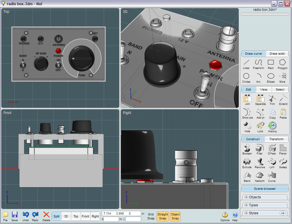
 Moi3D's
views
help you to visualize parts from a fixed or 3D angle and allow you to
move things at will.
Moi3D's
views
help you to visualize parts from a fixed or 3D angle and allow you to
move things at will.
I was able
to accurately size components to ensure that they fit inside
of the box too.
 The user interface is among
the most simplistic and intuitive of any 3D modeling program.
The user interface is among
the most simplistic and intuitive of any 3D modeling program.
I
was now ready to print out the top-view at real-world scale using
the layout program CorelDRAW!.
I affixed that to the top of the metal housing and had a
template by which I drilled the exact sized holes.
 As expected
and to the millimeter, every part fit perfectly! (Thanks Moi3D!)
As expected
and to the millimeter, every part fit perfectly! (Thanks Moi3D!)
 I used a
"Baby Label Maker"(a common hand-held labeler) to denote each control
function.
I used a
"Baby Label Maker"(a common hand-held labeler) to denote each control
function.
There
is enough room in the bottom of the project box to add an additional
kit or two, such as iambic keying and touch-sensitive paddle
control boards.
An accurate
analog dial was affixed.
To
make the dial, first I taped down a sheet of paper. Then I ran through
a procedure by which I tuned-up into a "dummy load" and using another
radio with a digital readout,
marked the matching frequency on the piece of paper. The paper with the
calibrated marks was scanned and a dial graphic was made in CorelDRAW!.
The
dial graphic was printed in reverse on to clear inkjet film using an
Epson 4880 printer. The printed image is not waterproof, so a white
spraypaint formulated for adhesion to plastic encapsulated the printed
surface. This surface was on the reverse side, so what I ended up with
was a professional looking plastic label.
Very professional. With this, I have no need for a separate frequency
counter circuit. But....
Later,
after additional bands were added, there was no room to denote four
bands of frequencies. A log from 0.0-10.0 is now used as a reference to
a frequency chart.
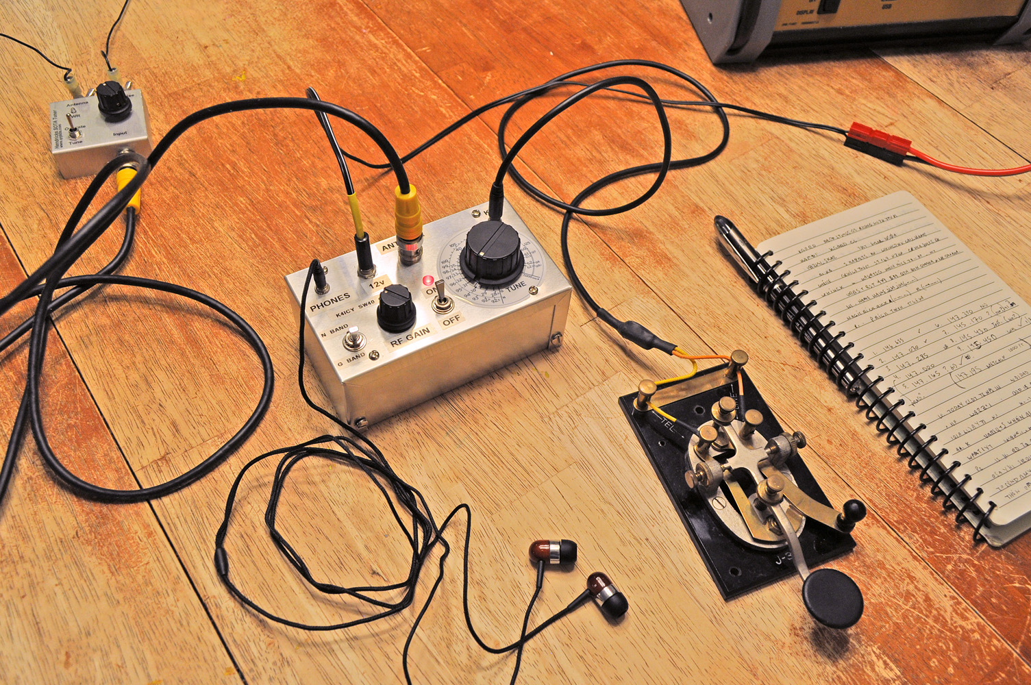
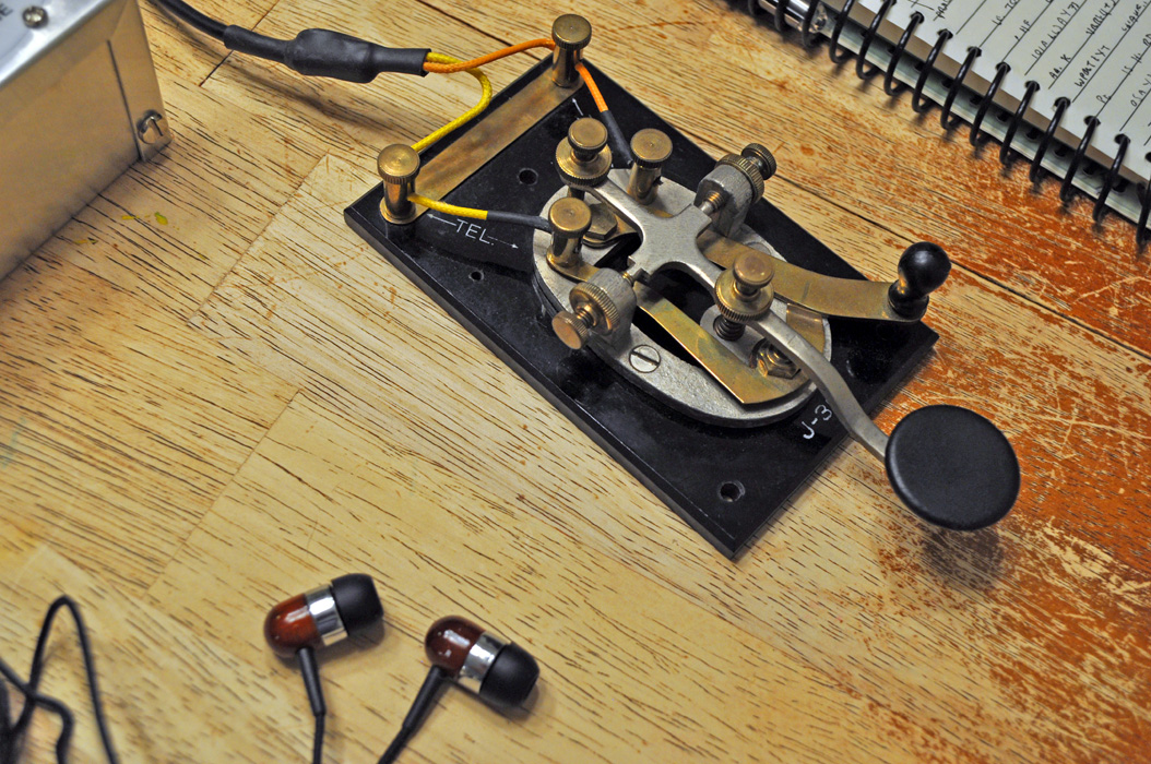 No station
is complete with out the Morse Code key and a pair of fancy ear-buds.
No station
is complete with out the Morse Code key and a pair of fancy ear-buds.
This is a World War II surplus key used by the Army Signal Corps. It
was passed down by my wife's late grandfather. (XYL's SK)
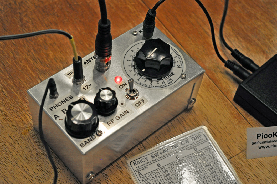
 Here is
the Small Wonder Labs "SW+40" QRP CW Transceiver in operation!
Here is
the Small Wonder Labs "SW+40" QRP CW Transceiver in operation!
The SWL SW+40 Fits inside of a small box and can be carried to any
location. This is PHASE 1.
Continue reading for more pics and continued tweaks......
Future considerations &
tweaks:
• Upping the power output if possible... [COMPLETED - See the Miniboots
Amplifier below]
With a few adjustments to the base SW+40, I could
only get
just a little over three Watts, but with any output
above 2.3 Watts
the signal output acted erratic, or maybe
it was
frequency instability - None the less, it looks like 2 Watts is the max
for this rig.
There is a power mod presented by KC8AON http://www.angelfire.com/electronic2/qrp/swmods.html
I attempted to try his component value changes but was
unsuccessful.
The max output voltage was now then limited to 2 Watts. Yes, the signal
was stable,
but not increasable. --- The SW+40 was designed to
work
optimally at 2-3 watts, if you exceed this, signal distortion will
occur.
• An outboard audio amplifier with speaker, which would be great for
Elmering opportunities. [Purchased a device to do this - would like to
homebrew one]
• An RIT (Receiver Incremental tuning) control. [only if the
rig had a "zero-beat" detection device]
• Touch sensitive paddle
circuit for eliminating the need for an additional paddle or
key. [Tried one but
ran into RF-feedback issues - will not proceed]
• A nice compact sealed
lead-acid battery pack would make this rig more portable. [COMPLETED - will
consider a Lithium Ion cell]
•
Consideration for using a different method of frequency selection. At
the moment I'm using a bank of NP0 capacitors on a rotary selector
switch,
But I may try widening the bandwidth by
changing C8 on the SW+40 board and replacing the band selector with a
fine-tune potentiometer.
[Widening the bandwidth would not be good. -
perhaps temperature compensations]
•
Would like to add a "Zero-Beat" indicator. This may be
implemented within the enclosure of a amplified speaker, but a single
RGB LED could be implemented within the SW+40 case.
• Would like to replace the on-off toggle switch with a three-position
switch (2P3T) so that the middle setting would set the SW+40 to
'receive only' to inhibit transmit, The switch would cut the
keying line between the Pico-Keyer and the SW+40.
Completed Tweaks:
• 01/28/12
- I added two more bands to make a total of four, essentially
broadening coverage of the whole 40m CW band from 7000 kHz to 7125 kHz.
I
purchased a 6 position, 2 pole rotary switch from Radio Shack. I needed
only four bands at 30 kHz width each.
I then tried to find a way to modify the part so that it
would only have four positions... After trying different methods,
including trying to add a stop screw,
I discovered that I could move
a stop tab on the spring leaf that allows the switch to rest in each
detented position. I was able to bend it temporarily over the a stop
and the part was essentially reversed. Now with the spring leaf tab
caught on the reverse side of the stop tabs - I created a 4 position
switch.
Consequently, other mods can be made to that type of rotary switch
yielding other combinations including a 12 position version!
I
was then able to bank clusters of matched picofarad capacitors to each
of the posts. Matching was not absolutely perfect, but 99% access to
the band with a good amount of precision ain't half bad.
•
02/24/12 - Completed a Tayloe Battery Status Indicator from Hendrix
Kits. It has an LED that changes colors based on voltage
thresholds.
With this, if the indicator is green then I know I am
getting out full wattage. If it is orange, then I'm working on borrowed
battery life. If the light is red, then I should shut down and
re-charge the battery, since proper operation of the radio cannot be
guaranteed.
• 02/26/12 - Completed trial on using a 1k potentiometer
to attenuate the AF output - thus protecting my ears with strong
signals.
• 02/28/12 - Completed constructing and running initial
tests on a KD1JV Digital Dial / Frequency Counter with 4-digit LED
display.
I still need to calibrate the DDial and set the offset
parameter, but this promises to give my full-band QRP radio an accurate
tuning dial and provide more enjoyment of use.
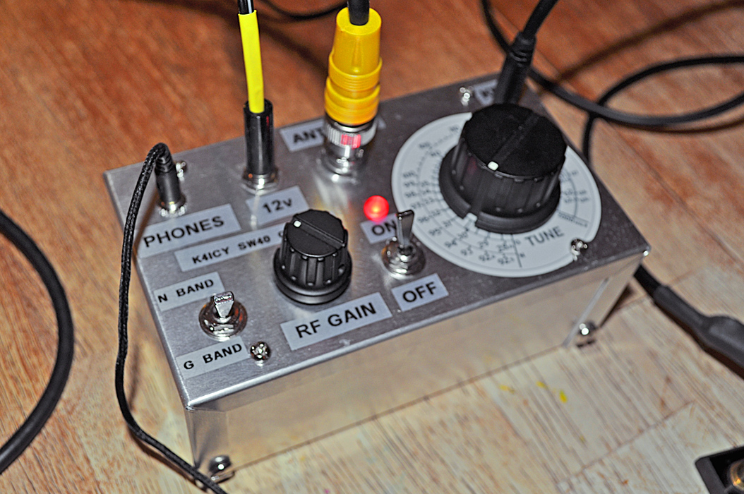
•
02/28/12 to 03/31/12 - PHASE TWO REVISION ON THE SW+40. Now called the
"Ice Box" for fun, it is a very sleek looking rig with many new
features:
Added an "AF Gain" control (Volume) to the
audio. Strong signal were tough on the ears, but now are controllable
using a potentiometer right at the output.
At the moment I am using a 5k ohm
potentiometer but it is too large and I'll put a 1k in there soon.
Added and finalized the KD1JV Digital Dial. My computer
tweaked
positioning did not take into account the sized of the Radio Shack
stand-offs.
I hand-filed each stand-off down to
0.3" in height and shaved 0.2" off of the sides of two so that the case
could be closed.
I had an older digital alarm
clock that was put out to pasture. It has a red diffusion sheet that
has adhesive on it which I used for the LED display.
Added a Pico-Keyer Plus, or actually purchased
just the chip and used a prototype board to build it's circuit.
Added a Tayloe Battery Status Indicator to tell me
when the input voltage in under an acceptable level.
With this, just to be cool, I replace the ugly
orange/green LED with a Full-Color LED. Since it's common pin
arrangement was the anode type instead of the
cathode type it was designed to operate, I used a couple of
transistors and a few resistors to get my K4ICY signature color
arrangement of aqua, white and red.
A new case was needed... This time I took care of
design the arrangement of the controls for logical usage.
The tuning knob has a clear berth and there is
also room
for the Digital Dial. The jacks and connectors were placed on the sides.
A clean coat of aqua colored spray paint finishes
it off.
Yes, I made a rectangular opening for the dial.
RG-174 Coax was used to make runs for some of the
more RF/Capacitance sensitive connections.
•
04/10/12 - Moved the PicoKeyer-Plus audio line from the junction of
R9/R10 on the SW+40 directly to the headphone audio hot side.
Bypassing the filter capacitor through a single
electrolytic. Eliminated the key-down "Chunking" issue cause by its
previous connection.
Audio filter is not really necessary
since the tone is only present on PK+ menu selections.
• 04/11/12 - Added a 1.5 Mega Ohm resistor from pin 3 of the
PicoKeyer-Plus chip to circuit ground.
There was a initial key-down and activation of the
transmitter upon the rig's power-up that would last a split second.
This was due to a lag in power availability to the
PK+
chip as other circuits in the rig were also powered up.
The keyer control MOSFET was left momentarily
unstable and
the resistor acts as a "pull-down" stabilizer to keep the gate turned
off until the PK+ sends a positive signal.
Generally, the PK+ is designed to run off of a continuos
on-board
battery supply voltage, but in this case, it feeds from the rigs
external power source, which takes a bit to begin feeding the other
area of the rig, especially larger capacitors.
•
04/12/12 - Added a small filter circuit to the positive power lead of
the Digital Dial. My attempt was to reduce the digital has noise
created by the dial's multiplexer.
I used a
resistor, electrolytic capacitor and a small choke. However, after
adding this mod, I only noticed a very small reduction in noise.
Unless I place the digital dial in a Faraday Cage
(a metal
box that is grounded), there are too many other leaky sources of noise
and pick-up inside this crowded rig.
TWEAKED THE TUNING
SELECTOR. The frequency range was first set to cover an optimum 7000
kHz to 7125 kHz, when I installed the parts in the enclosure, some kind
of capacitance was added and shifted everything down from 6xxx kHz to
7119 kHz. This was bad. The RG-174 coax cable that connected the
selector bank to the rig was adding capacitance. FIXED! I
trimmed
only 1.5" from the cable and the band frequency range magically went to
7001 kHz to 7126. Really?!?
We can safely say that an inch of RG-174 is
enough to move the rig's operational frequency 20 kHz!
My
suggestion to anyone trying to tailor their frequency range on the SW+
::: Set the bandwidth as wide as you need with a single value NP0
capacitor directly to its contacts on the circuit board, and do the
tuning and band selection with banks of resistors and potentiometers.
Those are stable since the VFO is controlled with voltage at
that
part of the circuit. Will I plan to change over to this
method,
probably not since I have my frequency specs close to accurate with my
current configuration.
•
01/13 - Visited the shack of ham friend, Norm, K4GFD in Greensboro, FL.
I was getting bad harmonics from the signal of my SW+40, so
we
connected it to a very complex looking spectrum analyzer with all kinds
of bells and whistles. It has a built in dummy load and
attenuator. We discovered that the SW+40 was pushing nearly 5
watts on peaks! However, this came at a sacrifice of signal
quality. The final transistor in the SW+40 was getting pretty hot as
well. After some adjustment, including the power-level adjustment in
the SW+40, we determined that it was set way too high. Once we brought
it down, we were able to peak the output to a very pure 2 watts with
little harmonic artifacts. I would like to note that if you
choose to use the "volt-ohm" meter method as described in Dave's
instructions, you'll not be able to see if any of the signal is being
wasted before the final transistor amplifier due to inefficiency. One
the final amp transistors are pushed beyond saturation, you may have a
stronger signal, but it will create excess heat and splatter all over
the band! Do not consider these tweaks offered by other
builders
claiming that more power is yours by modifying the circuit.
If
you are really proud of the time and effort put into a fine transceiver
kit such as this, you'll demand nothing less that 'quality' over
'quantity'.
•
03/03/13 - Completed a multi-feature version of the NB6M
"Miniboots" QRP-Gallon amplifier: http://www.amqrp.org/kits/miniboots/miniboot.htm
The Miniboots is an outboard RF amp based on the inexpensive
IFR510 (readily available at Radio Shack) that can
take 1 watts from any QRP rig and boost the output up to 12-14 watts
(at 14 volts).
A relay controls the transmit/receive with an RF sensing
circuit,
so the mode of CW operation is semi-QSK. After a month of
experimentation and building, I now have a linear amplifier and a
controllable final power output from 0.1 to roughly 12 watts!
Since
the Miniboots amplifier requires only 1 watt input, I was able to
reduce the output setting within the SW+40 to less-than 1 watt.
The Miniboots comes in two configurations, one with a
step-up/impedance matching transformer and one the other with an
attenuation resistor pad depending on whether you have a QRP (<5
-
>1 watts) or QRPp (< 1 watt) rig.
More info
and pics soon!
• 03/14/13 -
Completed building the Elecraft T1 - Automatic Antenna
Tuner. This tuner can tune HF-6m with an input of 0.5 watt to
20 watts. It took me five nights to build. It's very compacts and
stuffed to the gills with 15 micro-mini latching relays and nine toroid
assemblies. I was surprised myself when it actually worked
and so far I've used it on my SW+40 as well as my Yaesu 857-D at 15
watts. The T1 also gives information on SWR and power output.
(SEE PICS
BELOW)
•
05/13 - Completed several enhancements to the complete QRP setup:
Purchased a tool-bad at the surplus store to hold everything
in.
I cut a shape from a piece of surplus plastic using as footing in a
camouflage netting system to make an antenna wire caddy. Set
up a
sealed-lead-acid batter (3.3ah) along with cabling and fuses to run the
SW+40 and amplifier. Other accessories included.
•
01/11/14 - Tweak to the SOTA Tuner. Replaced the original
wing-nuts used for the terminals with multi-type banana-plug terminals.
• 01/20/14 - Replaced 5k ohm 'audio-taper' potentiometer used to
control audio output volume with a 1k ohm 'linear-taper' augmented with
a 1k ohm fixed resister to create a better custom response to the audio
drive of the SW+40. Tweaked resistor value of Pico-Keyer tone
line fed into audio. I am happy with the audio volume control
with an improvement in the SW+40's side-tone feed. If I can
filter the beep tone from the Pico-Keyer, I may consider using it
instead and muting the on-board side tone, but this is not a priority.
• 03/01/14 - Added labels to describe functions of each control.
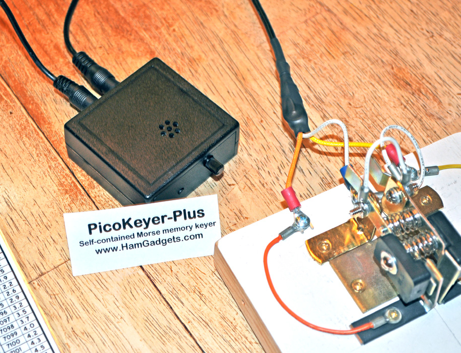
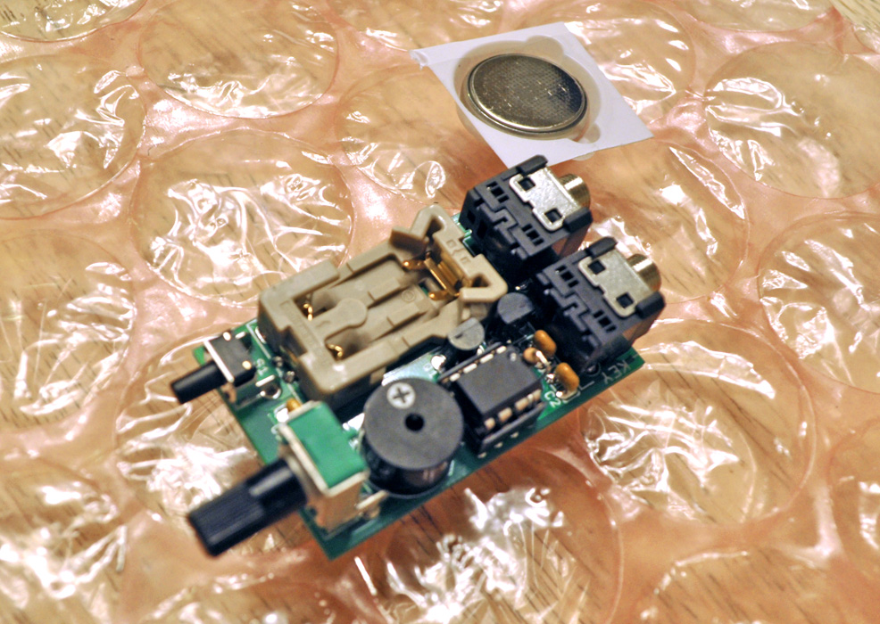 This
is a finished PicoKeyer-Plus from Hamgadets.com
This
is a finished PicoKeyer-Plus from Hamgadets.com
The
PicoKeyer-Plus is a very compact device that provides iambic keying
"dits" and "dahs" from your side paddle to any radio originally
intended to
work with a straight key.
It is also comes with four programmable keying text memories as well.
For only $18, it is very easy to construct this kit and is rated by
Hamgadgets to be at a "beginner's degree of challenge".
It
will also run independently for months if not a year from a standard
coin-type lithium battery, and can handle up to 60 volts of positive
keying in your radio.
I ordered this kit not for the inside of my QRP rig but as a
stand-alone to operate radios such as my Kenwood TS-130SE.
It also makes for a great code practice oscillator for using a paddle.
It will also auto-detect a properly wired straight key and will
automatically switch to straight key mode.
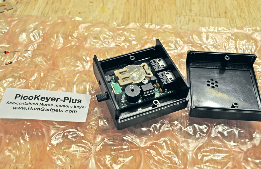 This is the keyer installed in
its attractive plastic case. This is the keyer installed in
its attractive plastic case.
For $8 you can get a plastic case that has all of the holes pre-drlled .
It's also
pocket-sized.
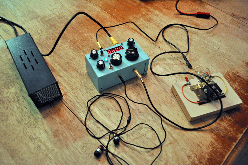
 Here is the completed Phase
2.
Here is the completed Phase
2.
A
modification or two has been added: The entire 40m CW band is now
accessible with the help of the rotary capacitor bank selector switch.
The paired PicoKeyer-Plus allows for iambic keying.
Time
to implement PHASE 3 :::
This
is the N7VE Tayloe Battery Status Indicator Kit.
Another fine kit from Hendicks QRP Kits at qrpkits.com.
This
circuit Illuminates a Tri-Color LED according to user-determined
voltage level thresholds. You can also illuminate separate LEDs if you
wish.
In my case, I'm using a Full-Color LED purchased from Radio
Shack allowing me to light it an aqua color to indicate a good supply
voltage level of
12+ Volts.
The LED shines white when the level starts to drop below
12 volts, and becomes red when the voltage drops below 10.5, at which
level, it would not be advisable to operate the SW+40's transmitter
section. The circuit is designed to use an LED with a cathode
(-)
common, but the Full-Color LED ties its red, blue and green sections to
an anode (+) common. Thus, I had to use the BSI to turn on a couple of
NPN transistors configured to drive LED's. Those were used to then
control the elements in the
Full-Color LED.
This
board is tiny, so I actually soldered it to the prototype board along
with the PicoKeyer+Plus using expelled component leads as board traces.
Do
not fear learning how to use transistors to do your bidding, there are
kits, manuals, courses and online information to help you learn.
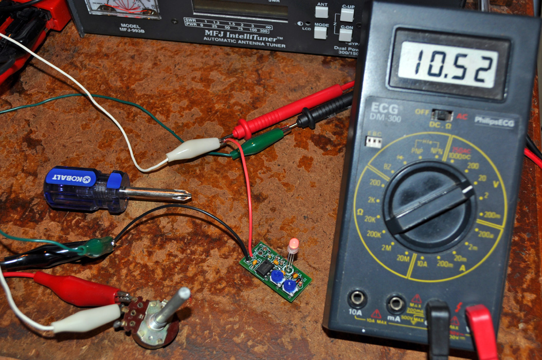 Here
is the BSI circuit under test.
Here
is the BSI circuit under test.
I
used a potentiometer to "dim" the voltage to the circuit triggering its
threshold levels determined by trimming potentiometers on the board.
The
tricky part of not using a controlled voltage supply was dealing with
the swings in voltage caused by current changes from the activation of
the LED segments.
But I made it work.
 This will be
the sub-board under construction.
This will be
the sub-board under construction.
This prototype board was used to incorporate the PicoKeyer-Plus, Tayloe
BSI, audio matching and other minor circuits.
 MoI
3D put to good use again!
MoI
3D put to good use again!
With
this simple yet powerful 3D CAD tool, I was able to work out both the
functional ergonomics and the exact placement of the "Ice Box's"
controls and components.
 Crucial
spatial alignment...
Crucial
spatial alignment...
Since so much more was to be stuffed into the small project box,
component placement had to be right on the money.
I had to take more care this time to get and accurate
representation of the exact sizing and proportion of each major part.
I
was able to make mistakes and revisions in the "virtual world" first
before work was done.
In
actuality, there are always unforeseen details, and objects are always
smaller on the screen than in real life. I would run into slight
problems later.
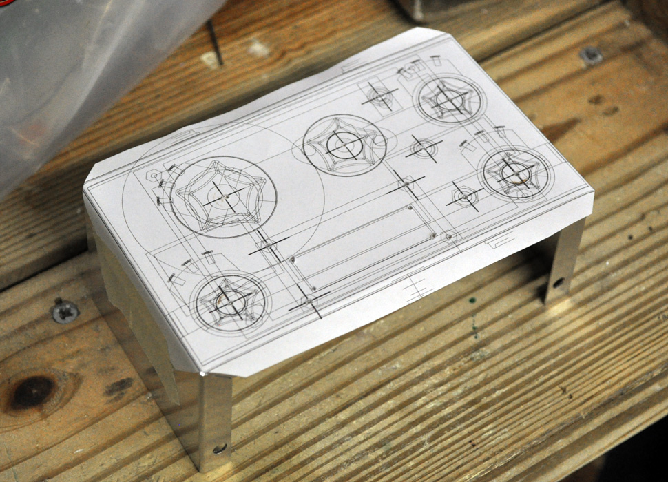 Drill
template.
Drill
template.
From MoI 3D, I exported an .AI file of the top-view to be brought into
CorelDRAW! for printing.
There was really no way to make a mistake with measurements because the
printout was "life size".
My
method for creating the holes for components involves first drilling
with a 1/16" drill bit. Second, increasing the drill bit size until the
final diameter is met. And third, using an array of metal files to
fine-tune and de-bur. The rectangle hole for the Digital
Display
was not that hard to manufacture. (No, there is no such thing as a
square drill-bit) A large hole was made in the middle
and metal files were used to "square out" the remaining area. The
aluminum in the Radio Shack project box is very soft.
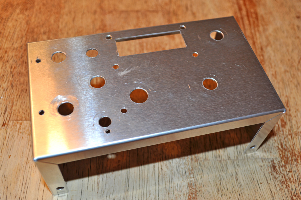 Here
is the final drill and file work.
Here
is the final drill and file work.
Thanks to the template, the drill-work was accurate to the 100th of an
inch.
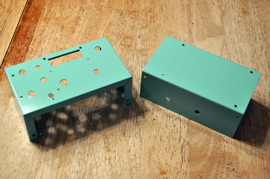 Finished
enclosure ready for components.
Finished
enclosure ready for components.
A
test fitting was made with the components and minute adjustments were
made. The enclosure parts were then sanded with fine-grit
paper
and painted first with a primer and then a few coats of the colored
spray paint of my choice. This color is Krylon's Blue Ocean
Breeze, a nice light aqua color reminiscent of the color used by some
old Volkswagen Beetles and vintage appliances.
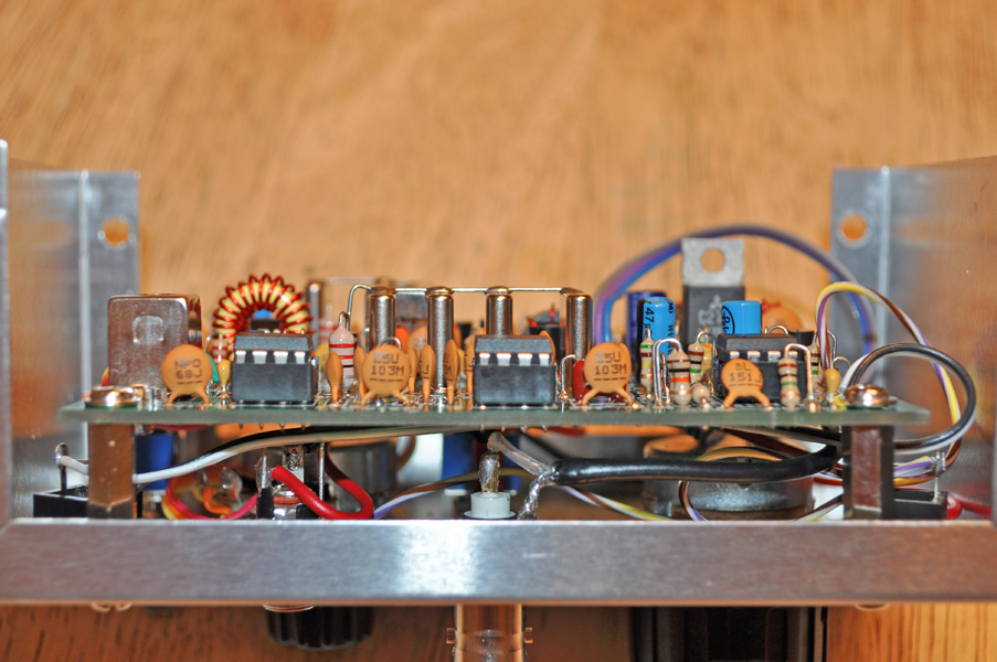
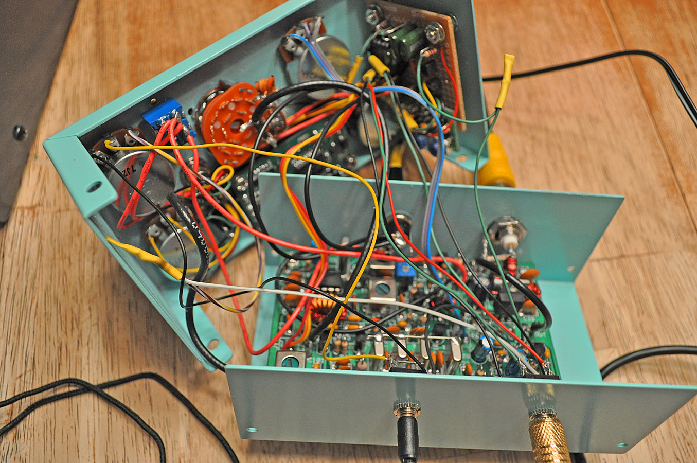 The internal
wiring.
The internal
wiring.
The
steps to make it to this point were many. This was the culmination of a
month of work. The large board in the bottom half is the Small Wonder
Labs SW+40. The small board in the middle-top of the top half is the
Digital Dial and the prototype board is affixed to the side of the case.
As you can see, the SW+40 PCB was offset to accommodate placement of
the prototype board.
Wire
management was my largest tackle. I ended up with redundant ground
wires and I am also left with an uncertainty that a few wires may be
free to be too close to function correctly in RF transmission
situations. This problem would become apparent later as installation
was finalized.
A
closer view of the component placement.
Most
of the components landed where they were intended. A large obstacle
were the stand-offs for the Digital Dial. I spent a good day filing
them down to exact dimensions.
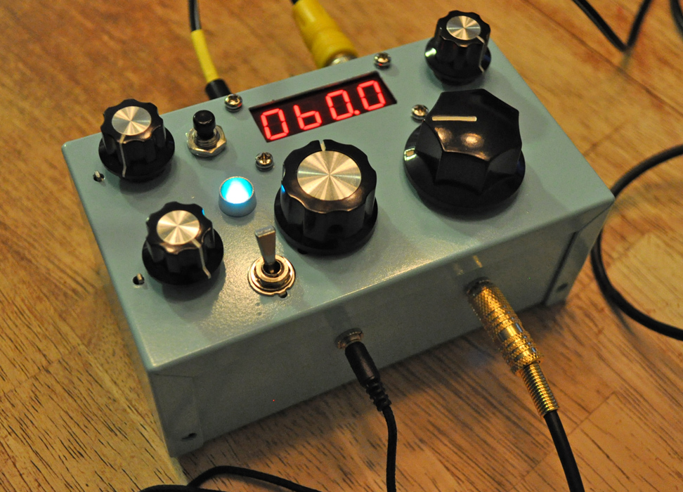
Here
is the final station setup for the new "Ice Box" QRP CW station!
 This
completes PHASE 3.
This
completes PHASE 3.
The
paint job came out nice, and the aqua-colored LED is a nice touch.
Yes, the paint will chip and scratch easy. Only
powder-coating
could make for a resilient surface.
The voltage indicator using the LED works well, as does the band
switch. The Digital Dial is also accurate to 100 Hz.
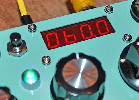 A
close up of the KD1JV Digital Dial.
A
close up of the KD1JV Digital Dial.
Here is a close up view of the KD1JV Digital Dial available from
Hendricks QRP Kits at qrpkits.com
This
kit is NOT for the faint of heart! The majority of the parts
including the 20+ pin microprocessor chips are SURFACE MOUNT and half
to be soldered to the sub-straight with either SMD past and heat
methods or a very small solder. I used 0.15" diameter silver-bearing
solder found at Radio Shack. Though I have to say that the sales clerk
said that it was not on in the system and couldn't figure out why they
had it. Their smallest was 0.22", but that will work too.
The red
diffusion lens was found on a discarded digital alarm clock. It was
adhesive and peel right off of it's original clock display.
Since
the stand-offs were filed to an accurate height, the Digital Dial's LED
display sat just below the opening with enough clearance for the red
plastic film.
Installation
notes for connecting the KD1JV Digital Dial to the Small Wonders Lab
SW+40:::
The
instructions for the Digital Dial don't go into much detail concerning
how to get this thing to work with any particular QRP rig on the market.
There
is NO place on the SW+ board for getting an IF signal, that will not
only provide a good frequency to subtract from the VFO frequency, but
since the IF in the SW+ is crystal controlled, you cannot change it by
the 800 Hz + which is the offset of the VFO. Even if you
cancel
the 4 Mhz signal reading from the VFO, the resultant display reading
will still be 800 Hz above the transmit frequency. The transmit
frequency is the number you want on the display.
By the way, the place to connect the signal lead
from the Digital Dial is at PIN 6 of U1
(First RX Mixer), the SA612 - or any circuit trace on the board
directly connected to pin 6. Use the provided 5 pF blocking
capacitor provided, one end connected to pin 6 and the other to the
cable's center lead.
Use small coax
like RG-174 and tie the shield ground to any nearby ground terminal on
the SW+ board.
To
program the IF Offset - There is no need to connect the signal sense
lead to anywhere else on the SW+. Short out the two pads on
the
Digital Dial marked "SW Offset" to enter the IF programming mode. Click
the Mode switch on the other side until the "LO - b"
appears. This tells the DD to give a reading that is VFO - IF.
Tune
the SW+40 VFO until the frequency of (7)"000.8" is displayed. This is
7,000.80 kHz. Click the Mode button and keep it held closed until the
display changes.
Now the offset of 7000.8 kHz
has been programmed in and it will be subtracted from the true
frequency reading giving you the correct operating frequency reading.
Note: Anything
below 7,000.00 kHz will give a strange reading. You don't need to go
there anyways!
Also,
when pressing the mode button to go to the Mhz display mode, the
display will give a strange reading. Since you are using a single band
rig, there is no need to see the "7". I
simply chose not to install the mode switch accessible through the
control panel. A pushbutton with a tall tab is provided, but since it
is not needed, either solder it underneath the DD's board or put a
switch with a different orientation as I have.
I
also suggest to install the following parts to the opposite side of the
board from which they are in the instructions: The mode
switch,
the electrolytic capacitor and the trimming capacitor. If you're going
to mount the dial to the underside of a panel, placing these items on
the opposite side where they can be better accessed will prove useful.
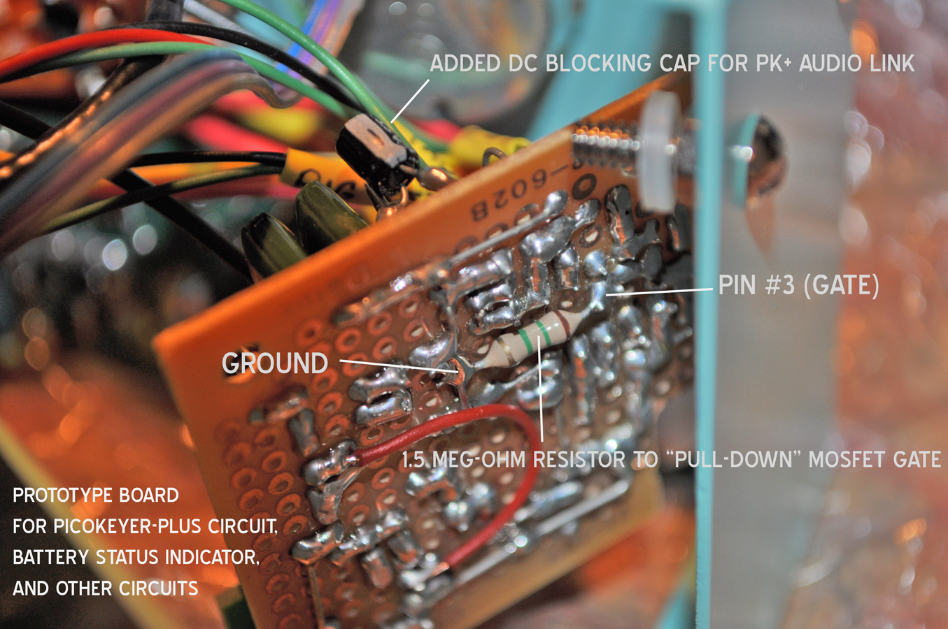
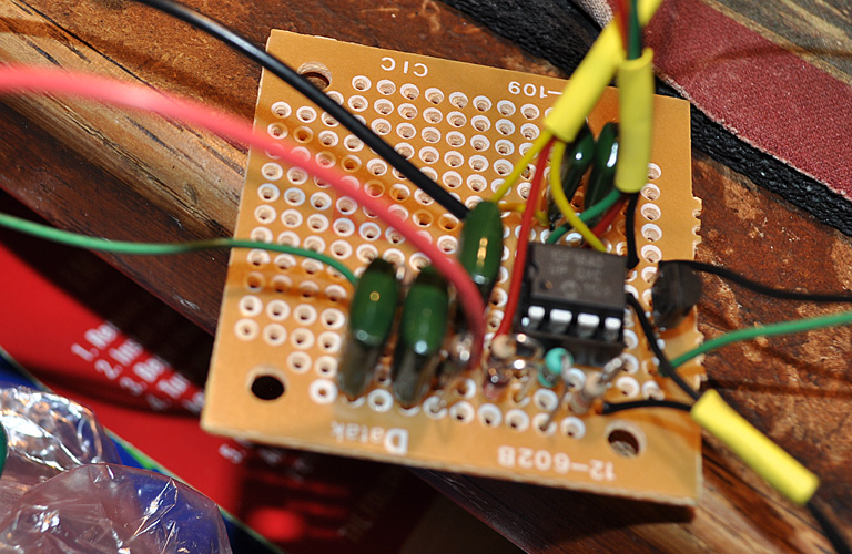
This
is a close-up view of the prototype board that houses the
PicoKeyer-Plus, the Tayloe BSI, the LED control circuit, and other
simple sub-circuits.
The resistor soldered to the bottom is the 1.5 Mega Ohm "pull-down"
stabilizer resistor for the gate of the keyer 2N7000 MOSFET.
Normally,
the logic circuits within the PIC PK+ chip are enough for on or off
operation of the 2N7000's gate, but the power availability of the rig's
power to the chip is initially limited and available power is ramped
up. The added resistor eliminated the problem of the transmitter going
into temporary key-down when power is first provided.
Above, there
is a small 100uF electrolytic capacitor which provides audio with DC
blocking to the PK+'s audio out to be fed to the receiver's headphone
audio line.
The PK+ provides it's own side tone, but this is disabled through it's
programming menu since the SW+40 already provides it.
However,
since the PK+'s menu/programming system works with an audio response,
those sounds must still be audible. Audio quality of the menu tones is
not critical, of course.
THE
"MINIBOOTS" QRP LINEAR "GALLON" AMPLIFIER
 I started the "Miniboots" amplifier project "dead-bug" (or
"ugly") style on a copper-clad PC board.
I started the "Miniboots" amplifier project "dead-bug" (or
"ugly") style on a copper-clad PC board.
This circuit is
based on the NB6M "Miniboots" design by Wayne McFee, no longer in
production as a kit.
For more information and a
circuit description on the NB6M Miniboots Amplifier - please visit:
http://www.norcalqrp.org/nb6mminiboots.htm
Here is a copy of the
Wayne McFee, NB6M "Miniboots" circuit:
The version shown here
works best on QRPp transmitters.

The circuit I used
(below) was the resistor network version meant to lower transmitter
output of more than at least 3 watts.

[Once
Completed] This vesion allowed me to set my SW+40 at a very
cool
0.7w input yielding an even 5 watts (QRP) from the amp.
Other variations can be
found at:
http://zs6rsh.blogspot.com/2013/12/nb6m-miniboots-zs6rsh-version.html
http://www.qsl.net/kd7rem/5wpa.htm
http://www.pivot.net/~acarr/ron/miniboots.htm
Using the copper-clad board allowed me space to alter parts where
needed. The heart of this
QRP-level "Gallon" linear amp is based on the cheap and readily
available IRF-510 power MOSFET.
Toroid cores were ordered from
Amidon Inductive, Inc. The resistor wattage types were chosen
to
handle the initial two watts input through an attenuation 'pad'.
Eventually, the drive level in the SW+40 was curbed to only
0.7
watts,
ensuring that the final transistor in the SW+40 would run more
efficiently. The Drive Adjust pot makes for a good
wattage-level
control but should be adjusted for 1:1 SWR at the transmitter.
I've made a couple of tweaks (not shown above) to better match the
Miniboots to my SW+40: The above circuit uses a step-down
transformer to attenuate power, but I used the attenuation network
shown in the two-band circuit shown on the NB6M site. Instead
of
150 ohms, on the pad, I used 120 ohms to make a more accurate 50 ohm
match. (a good online attn. pad calculator helps). There is a
33
ohm resistor shown on the drive adjustment for bias and I used a 100
ohm. These are just little tweaks made to better accommodate
my
SW+40.
The resistor attenuation network ensures that
the
SW+40 finals see 50 ohms of impedance! The "swamping" (or
biasing)
resistors at the gate of the MOSFET are 2x2 stacked 1/2 watt types
which together reduce the effects of heating. This may not be
needed, but it was worth trying.
The
main issue I had was tweaking
the low-pass Chebychev filter on the final. The input
impedance
from the MOSFET varies with both temperature and frequency. I
tried
several
models using the AADE Filter Designer software and also one or two
other ones I found in other schematics, but frankly, I'm not sure how
NB6M came up with his values... (I'm not an RF engineer) but with some
trial and error I came up
with a filter component combination
that gave me roughly 12 watts at a source voltage of 13.8 volts, while
also staying well within the limits of FCC rules on harmonic
suppression. However - all things out the window... the crux
of
packing anything dealing
with
RF into a small metal box is that now I have strange capacitances to
deal with and as of this posting, my output (with the SW+40 set at
0.7w) maxes out at 5-6 watts at the high-end of the band but tapers
down to near nothing at the low end!.
I should be able to lower the inductance on at least the
initial
toroid to see some improvement. Nonetheless, I'm at my 5
watt
"QRP" target for much of the QRP areas of 40 meters. I would
like
to rebuild this circuit (with some variation) with a
different enclosure at a later time.
 Here is a closeup view of the final portion or the
"Miniboots" amp.
Here is a closeup view of the final portion or the
"Miniboots" amp.
The IRF-510 (in its TO-220 packaging) got extremely hot even with this
clip-on heatsink.
 After I was satisfied with the results, I added the relay
which was controlled by an RF-sensing circuit.
After I was satisfied with the results, I added the relay
which was controlled by an RF-sensing circuit.
I had a chance here to play with the capacitor value that would
determine the 'Semi-QSK' dwell time.
 Proof of the "Miniboots" linear QRP amplifier in action:
0.7 watts in - 12 watts out (at 13.8 volts source).
Proof of the "Miniboots" linear QRP amplifier in action:
0.7 watts in - 12 watts out (at 13.8 volts source).
Now the tested circuit was altered for a more compact fit
inside of this high-quality aluminum enclosure.
Drilling, filing and fitting were the most time-consuming process in
completing my version of the Miniboots amplifier.
The
Drive Adjust pot (large knob) works for input signal attenuation
control and is intended to set the bias, it can essentially choose an
output level from
1 to 14 watts (when finalized). Control emphasis was placed
on
the 6 watt and below range using a non-linear pot configuration.
Also in the front is the control switch and status LED.
The
control switch not only controls power to the amplifier circuit but
routes the input RF line to a 2-watt dummy load to help protect the
SW+40's finals from accidental keying.
The LED is again, a K4ICY
custom! Using the small breadboard circuit (to the left), the
Full-Color LED shines a very bright aqua color when the amplifier is
powered up and in standby mode, then shuts off and shines red for every
keyed RF signal. Also, variations in output signal power due
to SWR will show a more varied
fluctuation in the red LED luminance. Once keying is stopped,
the
aqua
light waits a little bit so that you have a more visual indication of
your sending, then slowly re-lights. A nice N-type power
connector is on the back, powered via a 6-amp laptop DC cord.
BNC female RF connectors are on the sides.
My design goal was
to place the Miniboots amp within
a shorter project box affixed below the SW+40 box, which would have
provided space for additional goodies, however, the thick aluminum box
made for a very attractive stand-alone unit. When you add the
clunking
noise from the relay, the slight mount of heat from the MOSFET and the
other bulky parts, in a good way, the entire package has an imposing
feel.
 Click on this pic for a larger view...
On the far right is the dummy load
array (2 watts). The LED status board is on the far left and every nook
and cranny has been stuffed with the amplifier and RF sense circuits.
THE ELECRAFT
'T1' MINIATURE AUTOMATIC ANTENNA TUNER
 Here is shown the kit-building process for my new Elecraft
"T1" Automatic Antenna Tuner.
Here is shown the kit-building process for my new Elecraft
"T1" Automatic Antenna Tuner.
This
kit was too expensive to be included within the case of an amp or QRP
rig, and frankly, I don't recommend building this, but rather
purchasing the unit in completed form. It's tolerance are
almost
too tight for the actual parts supplied and there are simply too many
potential points of failure. I enjoyed building this kit
however,
but there were too many 'scary' moments. However, it worked right off
the bat! I recommend using an even thinner solder diameter
than
specified. Construction took five nights to complete.
Here is the final product. This thing is tiny
indeed - about the size of a pack of cards.
I
would have preferred to build a traditional Pi-network LC manual L/C
tuner and I may someday, but having an instant match without risking
the death of a QRP rig's fragile finals is fine with me.
 Here is my complete portable QRP station (for 40 meters) set
up on a table on my back patio.
Here is my complete portable QRP station (for 40 meters) set
up on a table on my back patio.
At
the top is a 3.3 ah SLA gel-cell battery, to the left is the T1 tuner,
the completed Miniboots amp is in the middle, and the SW+40 to the
right.
The
QRP Quick-Disconnect Antenna Kit
Making
the task of installing the antenna system for the SW+40 a more
enjoyable task...
I
cut a
custom shape out of a spare piece of military-hardened plastic (top
left) once used as a foot for camouflage netting system, allowing me to
wrap the antenna and counterpoise in quick fashion.
The SOTA Tuner (top right) has been modified with terminals that allow
for either banana-plugs, spade-terminals or bare wire. The
banana
connectors allow for instant connect and disconnect. The SOTA Tuner is
ONLY used when the antenna is connected, through it, to the
SW+40. It will handle a max of 5 watts, and currently, the
SW+40
is set for 0.7 watts (QRPp).
A small custom length of BNC coax feedline. (bottom left)
They
are not RG-58 (?) and I use three of them. I do not recommend
BNC
connectors as they tend to fail, but it is the universal standard for
QRP cabling.
A nifty accessory now used by many QRP enthusiasts (bottom right)
employs a BNC(female)-to-Banana(female) terminal. I purchased
this one at Fouraker's
on Appleyard Dr. in Tallahassee. The banana terminals allow for antenna
leads with banana plugs for quick connect/disconnect along with
utilization for spade-terminals and bare wire. I use this
terminal in conjunction with my "T1" auto-tuner when running more than
a few watts and it is not feasible to use the SOTA Tuner.
These
terminal adapters generally come with two holes located in the body
which actually allow for an additional pair of banana plugs to come in
contact with metal in the adapter, but I used them to pass a length of
parachute cord. I tied the ends after placing a spring-loaded
cinch which allows me to attach the antenna's base to a sturdy object,
such as a branch or table leg. These cinches are often found
on
small bags and back-packs commonly used with backpacking.
Once
deployed, if anything happens to the antenna the radio is sure to
remain safe on the table!
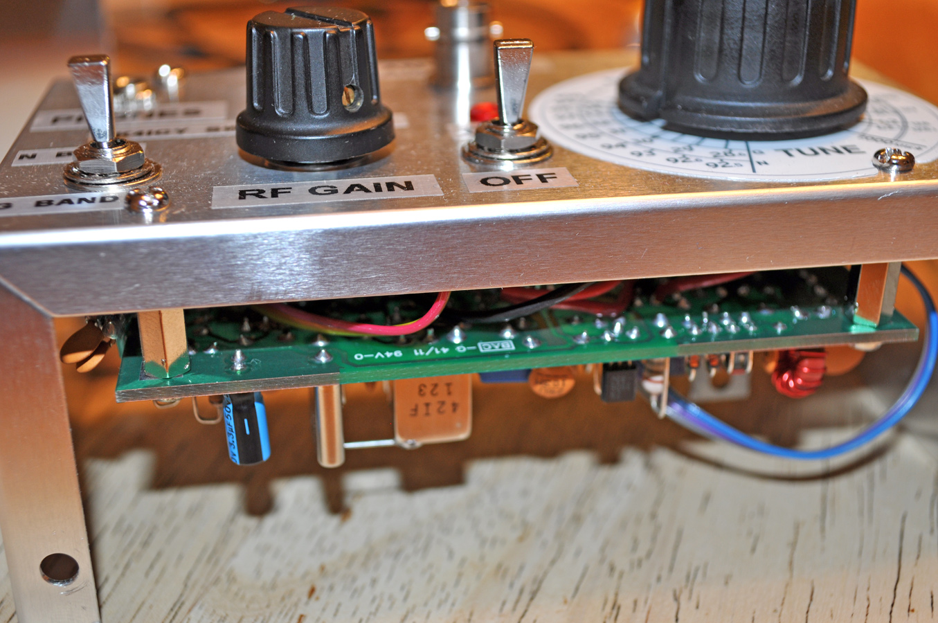
 Here is the "Ice Box" SW+40 with clear labels applied
I
was hesitant to add labeling to my SW+40 for fear of marring its
spartan look. It was always in the plans but I desired
something
more permanent and professional such as screen printing. I
have
the resources at work to have done this, but not with out some trial
and error and some risk to the product.
After showing it off at our
club's booth where we participated in the National High Magnetics
Laboratory's open house, it was clear I needed to expedite the labeling
process... well, with the 5000+ visitors that stopped by - giving TARS
our best PR exposure ever, I figure I had been asked enough.
I spent
a couple of hours Saturday night with my wife's Dymo label maker, some
clear label tape and produced the necessary verbiage.
Each label was cut down to close dimensions and affixed under each
control... simple.
At least the general ham has more of a chance of recognizing my radio's
controls. - I do feel
that it has lost some of it's Braun-esc design simplicity.
I believe that eventually, the labels will turn dingy yellow
or brown and peel off, but I can always re-paint it.
CONSIDERATIONS::
There
are still issues to resolve...
• There
is a digital hash noise from the Digital Dial. It has to be a good S3
in audibility. I have read to expect this as it might be coming through
the power-supply line, and there are methods already tried by
others to
remedy this problem. So far, my attempt at filtering has produced no
real results.
• Other improvements and
fixes involve changing the audio volume potentiometer from a 5k ohms to
a 1k ohms or less. [DONE
- improvement to volume control, side-tone and PicoKeyer beep tone]
•
Experimentation with a single band opened wide with a pair of highly
stable capacitors, using two potentiometers to hone-in on a more
precise and stable frequency.
More than a few ops I had
a QSOs with noted an
abrupt frequency shift which is due to the thermal instability of my
VCO and the array of capacitors I used, and I also believe a faulty
antenna cable has been at
fault for abrupt shifts.
• May consider
better internal wire management, and also bonding the two
case shells. I may also consider applying a toroid for
RF-blocking to the keying, audio and power lines.
•
The output low-pass filter on the Miniboots amplifier needs to be
modified to realize its potential 14 watt output. Though 5
watts
is the target for QRP, more is welcome sometimes.
•
A second case can be attached which would hold: 1) isolated class-D
audio amp and speaker 2) Lithium-Ion power cells (maybe 4) along
with 2-amp boost converter and charging/protection circuit 3)
Replace the Pico-Keyer with my Minty Keyer
4) Arduino-based tuning circuit... this one would use an Arduino
to control an IC-based RF switcher for select banks of trim capacitors
as well as providing exact voltages to the VCO.
EXCITING NEWS!
[01-15-18]
Rick Choy, N3HXT, at Midway Electronics
in Middletown VA has taken on Dave Benson's SW+40 and is now again
available for sale, now called the ME40+! Rick has
spiffed
up the original manual to have a "Heathkit" style to it and offers the
kit in 40, 80 and 30 meter versions with 20 meter version on the
way. Visit http://www.midwayelectronics.us/qrp/index.html
or contact Rick at midway7726@gmail.com for more
details. You can order the MExx+ on eBay as well as Rick's
website.
Other
than a few minor remaining issues - I'm very satisfied with the results.
I
do not plan to immediately continue development on the "Ice Box (Phase
3)", with the exception of adding labels or screen printed markings.
The box has now been closed and I plan to take it into the field and
work some QRP slow-speed CW.
Everything
seems to have come together well with this project and the integration
of these many kits are a testament
to the ingenuity of their creators.
Special thanks to the
kit creators and vendors for their helpful
correspondences and technical support :::
Dave Benson K1SWL
- Small Wonder Labs / SW+40 CW Transceiver Kit [Site and kit
no longer available...]
Please visit Rick Choy, N3HXT's Midway
Electronics for the new ME40+
Dale Botkin N0XAS
- PicoKeyer-Plus / Iambic Memory Keyer - hamgadgets.com
Steve Weber KD1JV
- Digital Dial / Frequency Counter - qrpkits.com
Sumner Eagerman
WA1JOS - CW Touch Keyer - cwtouchkeyer.com
I
plan on having lots of fun furthering my learning of CW and making
great contacts.
Kit
building is a wonderful pastime, and learning basic electronics (even
if intellectually) should be a right of passage for all "hams".
73
DE K4ICY SK ••
Go build you own!
Edited:
03/19/20
©2020 Copyright - Michael A. Maynard
|


