ANTENNA
PROJECTS
Antenna alterations: Pics to follow...
• Flat-top dipole for 80, 40, 20m was reconfigured using only my yard
space and lifted to 60-75'
• A 2m Moxon was made and lifted to 45'. It's cut for 146.520 and made of
1/2" copper pipe.
• A Roll-Up J-Pole for 2m & 70cm was made from 300 ohm TV twin-lead.
Very effective. Up to 15 watts service.
• Field Box made with everything included, minus launcher to deploy
tree-bound antennas for emcomm and fun.
"Expect the
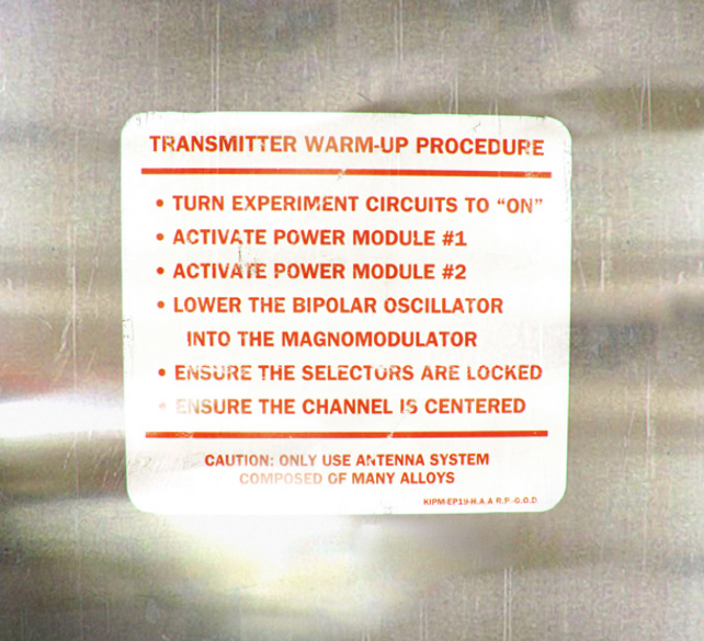
unexpected. And always transmit with an antenna of many alloys." - Alan Maxwell, KIPM
Antenna projects of K4ICY
The Fan Dipole antenna (see below) made it through TS Fay well
and the local hams were up to the charge! My antenna stayed intact through the winds. So
far since it's installation, I've made many contacts, both DX and cross country. And the
signal reports have been stellar!
It's really assuring when you jump into a pile-up and get picked out over other hams
with only my barefoot default power level. Aside from favorable propagation "it's
all about the antenna". Proper height and gain considerations are key as well.
The "Tee" Model - See how I constructed
this strong and reliable dipole center connector:
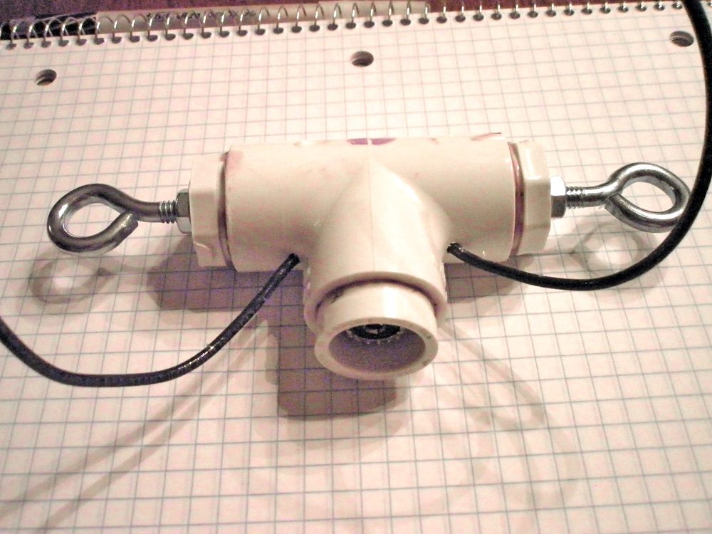 Here... Here...
You don't get smaller than this for a home brew dipole connector made of PVC
parts... Photos inside...
The "Cylinder" Model - An easy to
construct dipole center connector for only !:
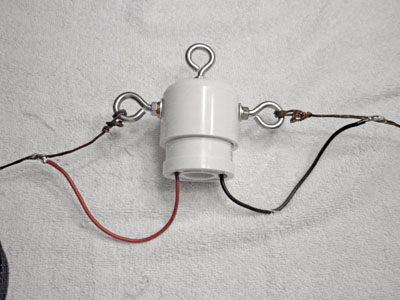 Here... Here...
Using relatively few parts available at the home supply store (minus SO-239), easy
to build and will hold a balun... Photos inside...
The birth of the fan dipole:
This
antenna served me from 2008-2011 until sadly, a pack of ravenous
rope-thirsty squirrels repeatedly dropped this installation.
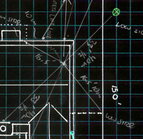
Take a look of my rough sketch for antenna placement
at the home QTH...
(Click to enlarge photos)
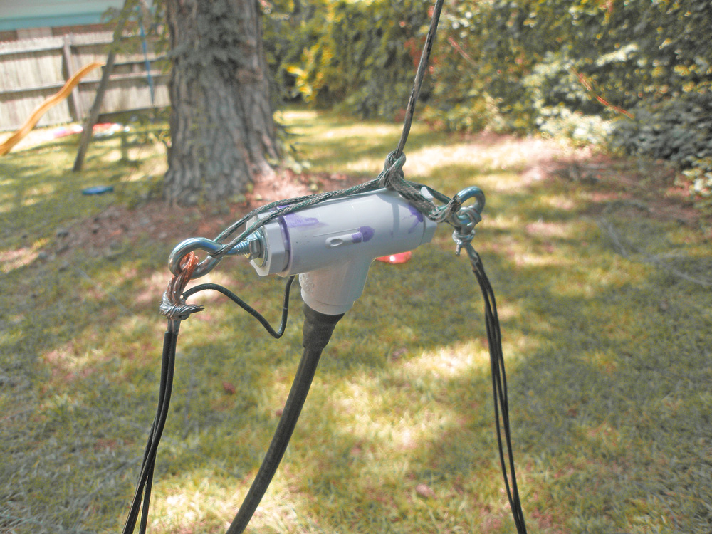
Here is the connector assemble with the dipole leads
and coax. Tied to a sturdy rope and coax-seal applied to the coax end.
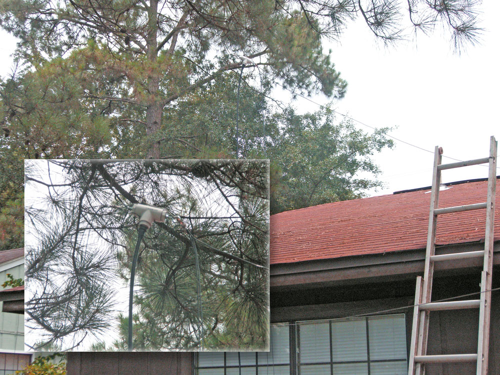
Here is the resulting use of the connector and the installation
of the multi-band fan dipole.
After getting the antenna up about 20' it's I had to take a
break and there it sits for a week or two. Since the 80m segments are already stretched
out I though I'd at leat test the SWR to see if I was able to get close to my target
resonant frequency of 468 / 3.815 mHz or at least 123' / 2.
I got on really late at night when the 80m band had died down, and I noticed right away
that the new antenna was more noisy. The procedure using the MFJ Automatic Intellituner
MFJ-993B goes like this. I went into CW mode and picked a spot where it was quiet and
waited a minute to see if there was anyone on. Then simple state: "Is this frequency
in use... (call sign) doing radio test." Some frequencies in exact places like 3.9
mHz were busy and you need to stay from the ends at leat 5 kHz so I had to compromise on
test frequencies. Note: on 80m CW you must key out "QRL?" With no reply key your
call and perform your tuneup. Thank goodness no one answered, I was in the mood to test,
it was 2am in the morning and I did not want to go into a full blown CW QSO. It also helps
to go at a slow 5wpm... Well, non the less, I was able to build a data table to SWR needle
reflection numbers. There is a straight foward formula but the MFJ's digital readout is
pretty accurate.
First I would test do the procedure with the CAR contol set for at least 2w PEP QRP
signal. This is a safe level and will give you an idea if anything is wrong with the
antenna system. The Blue line on the chart below shows that my target frequency is pretty
dead on and dosn't require me to cut back or add any length (yet). Since the antenna is
not up to 55' with all of the bands installed, I won't know until then, as there will be
much interaction between the multiple elements. Doing the test procedure again with the
CAR set to maximum calling "test" again produced the Red line on the chart. Two
things were noticed. First the results were different and second that without the tuner
activated the tranceiver uses Fold-Back protection and when the SWR was around 4 I could
only produce around 13w. 100w CW at 1:1 SWR as the TS-130SE only allows 100w on 80 for
some reason.
Notice that the lines invert as the frequency rises above the resonant frequency?
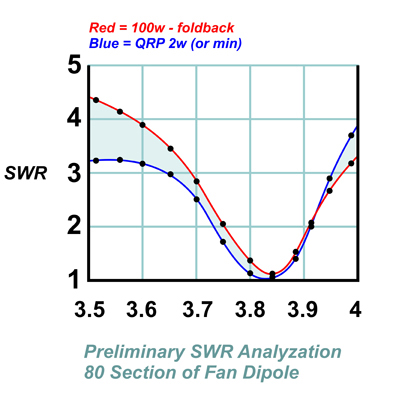
Final composite graph of SWR measurement #1
After getting the okay from my very nice neighbor, I could then go
foward with the project. Though I had to make a few changes in the antenna placement to
what is now shown in the map above. So I only had to use the tops of two of my neighbor's
trees, but right next to the edge of her yard which will minimally encroach upon the
neighbor's property.
It took all of the Saturday (two total) to hoist the remaining part of the antenna up.
Actually, I had to bring down the southern going 80m line and move it over some. This
allowed me to situate the 20m and 40m lines better and gave the 80m total line a
straighter path.
My sling shot broke so I was left with throwing the fishing weight up by had. Which proved
to be difficult but accurate enough after many attempts and misses. A launcher such as the
ones for tennis balls would have been overkill for my 1/2 acre yard and an archery set
would have most likely "killed" a neighbor, so with the weight it was.
First I'd get the weight and mono-fillament fishing line into the tree, then I'd pull up
lengths of this camping rope I found at Wal-Mart for 80cents a piece for 50' lengths.
Simply doubled them up if needed. And pulled the antenna wire out with that and held the
center connector up as well. This, when all was said and done gave me a nice flat top
fan-dipole.
Though, not the best choice for antenna. It was a good use of my
many pines and meager resources. I was hoping for the whole antenna to be put up 60' or
so, but now have to settle for half that! I believe it's about 35-50' up depending on what
line you're looking at. The trees in my yard are broadleaf pines and they're not
considered very ancient, so the branches get very encombered as you go up. This is a
problem when you have to toss the line over many branches hoping you don't have to re-do
them when you start to lift the whole thing up.
Here are the fruits of my labor: ...so far
Over the fomerly used 67' longwire, I notice a good 5 S-unit increase accross the board.
An increase with incoming signals, and an increase in noise too!
Though directivity may play a role, some hams were quite audible on the fan-dipole and
simply not there on the longwire. With my tuner, I shouldn't have too many problems
mitigating any of the antenna's shortcomings, but I still have to test and adjust for
optimal SWR and band performance.
As you can see in the graphs below, there is a little more work to do:
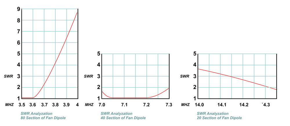
Typical of errecting any antenna with the "468/f" formula
you, have to go back, lower the lines and do some trimming. This is evident with the 80m
element test above.
Now the 40m test above is just beautiful! Nearly a flat response accross the whole
band. And the 20m section?.... It looks like the elements are too short!
Now this test wasn't as thorough and I made these readings while trying for contest
contacts and general QSO's. I do know that 80m needs some work! I suppose that loading a
dipole cut for 80 with other adjacent elements for other bands would increase the Q-factor
of its element. So at the least I'll try to move it's 1:1 area to the 3.8-3.815 area where
the DX window and the local Skywarn frequency are. If I can keep the 40m results where
they are, I'll be happy. What do I do with 20m? Maybe add some lengh to it's elements?
None the less, when I do tweak the 80m section, it will alter the tuning on the others, So
I'll have to remeasure a couple of more times to get it right. ...But isn't that half the
fun in ham radio?
Already, my station is really starting to perform like a real ham
station. And I'm hoping my contact ability goes up.
My next antenna dream would be to work around a good mast, a vertical? a multi-element
Yagi or quad?
I promised myself that I'd try to get my mobile operation more up to
snuff.
73! DE Mike K4ICY, See ya down the log!
|


